
Heatable lens for luminaires, and/or methods of making the same

a technology of luminaires and heat sinks, applied in the field of heat sinks for luminaires, can solve the problems of reducing the aesthetic appeal of the lite, difficult for shoppers to quickly and easily pinpoint products, and condensation buildup on automobiles, etc., to achieve rapid and uniform heating, reduce the associated lighting system's light output and efficiency, and high light output efficiency

Inactive Publication Date: 2012-10-04
GUARDIAN GLASS LLC
View PDF7 Cites 38 Cited by
  • Summary
  • Abstract
  • Description
  • Claims
  • Application Information

AI Technical Summary

Benefits of technology

[0007]Another aspect of certain example embodiments of this invention relates to a monolithic tempered coated glass solution that allows the glass lens to be rapidly and uniformly heated in a SSL fixture while also achieving high light output efficiency.
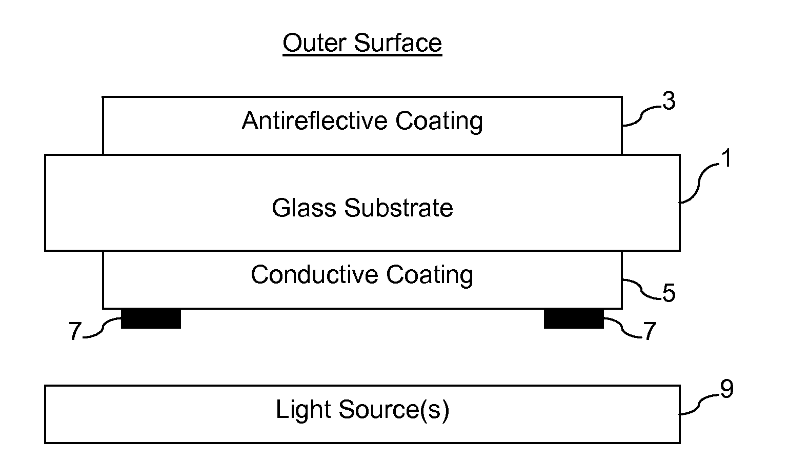
[0008]Certain example embodiments include a high transmittance conductive coating (e.g., greater than about 87% on clear float glass), that optionally incorporate a visual antireflective (AR) coating on the opposite side of the monolithic glass lens to further enhance light transmission (e.g., for another 4% point visible light transmission gain).

Problems solved by technology

Condensation buildup on skylights detracts from the aesthetic appeal of the lite.
Similarly, condensation buildup on refrigerator / freezer doors in supermarkets or the like sometimes makes it difficult for shoppers to quickly and easily pinpoint the products that they are looking for.
Condensation buildup on automobiles often is an annoyance in the morning, as a driver oftentimes must scrape frost or ice and / or actuate the vehicle's defroster and / or windshield wipers to make it safer to drive.
Moisture and fog on the windshield oftentimes presents a similar annoyance, although they may also pose potentially more significant safety hazards as a driver traverses hilly areas, as sudden temperature drops occur, etc.
In fact, given the widespread adoption of Solid-State Lighting (SSL) solutions and the fact that their light sources (e.g., LEDs) typically do not generate infrared (IR) heat (unlike some High-Intensity Discharge (HID), Incandescent, and Halogen light source technologies) when generating light, the condensation problem can be more severe, e.g., because of visibility and safety concerns.
It is believed that no SSL-based solution has been able to be used successfully on a commercial scale in applications where the lighting fixture is directly exposed and susceptible (close to ground level) to ice and snow build-up, and / or where full light output is critical for safety (e.g., airport runways, walkways, stairs, etc.), for example.

Method used


Image

  • Heatable lens for luminaires, and/or methods of making the same
  • Heatable lens for luminaires, and/or methods of making the same
  • Heatable lens for luminaires, and/or methods of making the same

Examples


Embodiment Construction

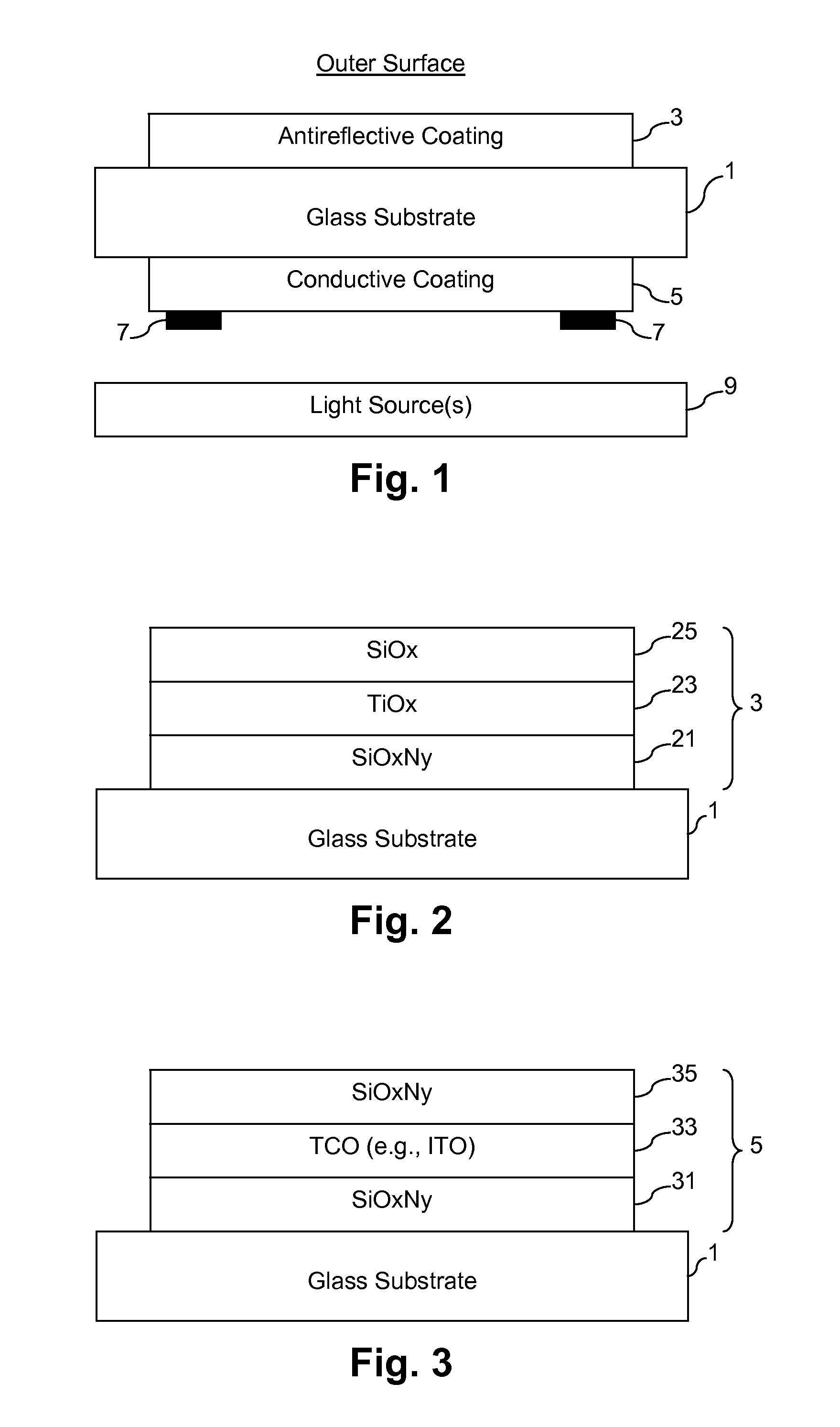
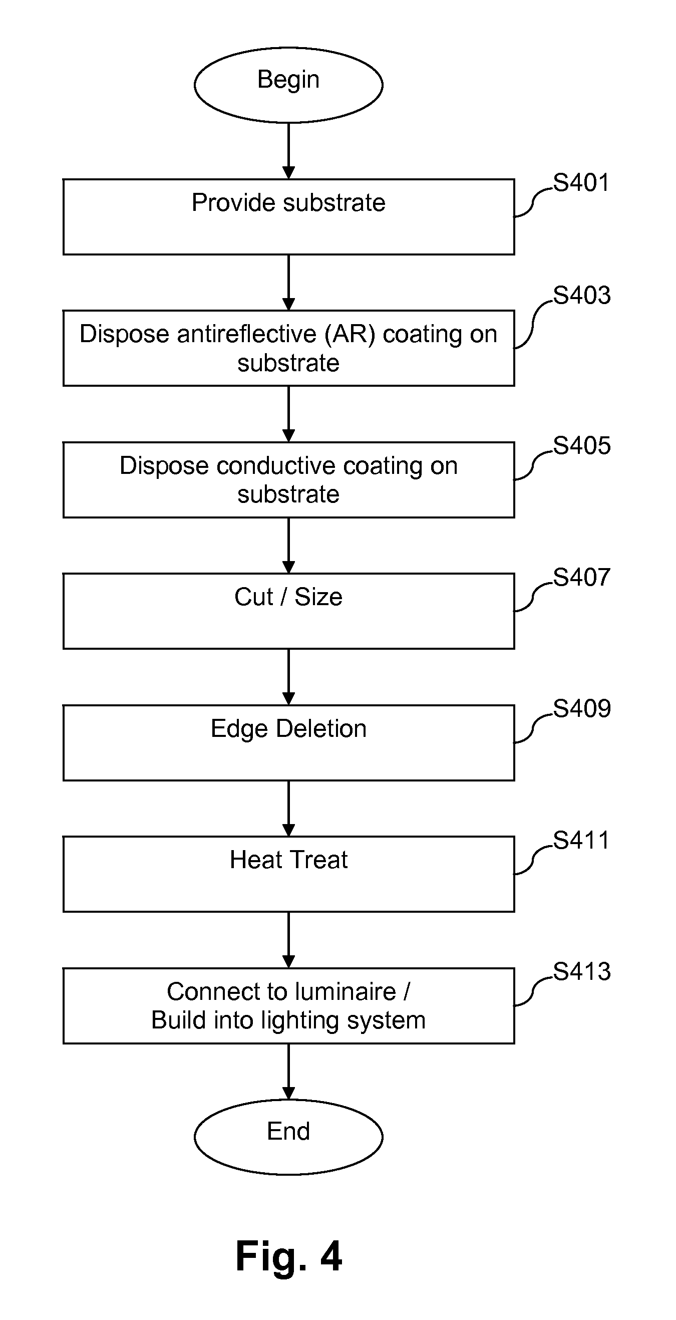
[0022]Certain example embodiments of this invention relate to heatable glass substrates that may be used in connection with lighting applications, and / or methods of making the same. In certain example embodiments, a glass substrate supports an antireflective (AR) coating on a first major surface thereof, and supports a conductive coating on a second major surface thereof, the first and second major surfaces being opposite one another. Bus bars connect the conductive coating to a power source in certain example embodiments. The substrate may be thermally tempered, e.g., with one or both coatings thereon. In other words, the antireflective coating and / or the conductive coating may survive thermal tempering processes.

[0023]Referring now more particularly to the accompanying drawings in which like reference numerals indicate like parts in the several views, FIG. 1 is a cross-sectional view of an example heatable substrate in accordance with certain example embodiments. As shown in FIG. ...


PUM

PropertyMeasurementUnit
thicknessaaaaaaaaaa
sheet resistanceaaaaaaaaaa
thicknessesaaaaaaaaaa

Abstract

Certain example embodiments of this invention relate to heatable glass substrates that may be used in connection with lighting applications, and / or methods of making the same. In certain example embodiments, a glass substrate supports an antireflective (AR) coating on a first major surface thereof, and a conductive coating on a second, opposite major surface thereof. Bus bars connect the conductive coating to a power source in certain example embodiments. The substrate may be heat treated (e.g., heat strengthened and / or thermally tempered), with one or both coatings thereon. The heatable glass substrate thus may help provide a chemical and / or environmental barrier for the luminaire or lighting system disposed behind it. In addition, or in the alternative, the heatable glass substrate may help reduce the amount of moisture (e.g., snow, rain, ice, fog, etc.) that otherwise could accumulate on the luminaire or lighting system.

Description

[0001]This application is a Continuation-in-Part (CIP) of U.S. patent application Ser. No. 13 / 333,183, filed Dec. 21, 2011, which is a CIP of U.S. patent application Ser. No. 12 / 926,714, filed Dec. 6, 2010, which is a CIP of U.S. patent application Ser. Nos. 12 / 923,082, filed Aug. 31, 2010, and 12 / 662,894, the latter of which is a CIP of U.S. patent application Ser. No. 12 / 659,196, filed Feb. 26, 2010, the disclosure of each of which are hereby incorporated herein by reference.FIELD OF THE INVENTION[0002]Certain example embodiments of this invention relate to heatable lenses for luminaires, and / or methods of making the same. More particularly, certain example embodiments of this invention relate to glass substrates that support antireflective and conductive coatings on opposing major surfaces thereof that help serve as chemical and environmental barriers to underlying luminaires and help remove moisture-related disturbances from surfaces thereof and reduce transmission losses relate...

Claims


Application Information

Patent Timeline
Patent Type & Authority Applications(United States)
IPC IPC(8): F21V5/04C23C14/06C23C14/35
CPCC03C17/3435C03C2217/70C03C2217/948B32B17/10036B32B17/10201H05B2203/013B32B17/10541B32B17/10761B32B17/10788H05B3/84H05B2203/01B32B17/10211F21Y2115/10F21Y2115/15C03C17/2456C03C17/3482C03C2218/154C03C2218/32
Inventor MAIKOWSKI, DAVID P.MCCLEAN, DAVID D.BOURQUE, TIMOTHYHOBBS, CHRISTOPHER
Owner GUARDIAN GLASS LLC
Learn More