
LED dimmer circuit

a technology of led dimmer and diode, which is applied in the direction of lighting apparatus, electroluminescent light sources, light sources, etc., can solve the problems of flickering and likely appearance of flickering

Active Publication Date: 2012-10-04
SEMICON COMPONENTS IND LLC
View PDF3 Cites 27 Cited by
  • Summary
  • Abstract
  • Description
  • Claims
  • Application Information

AI Technical Summary

Benefits of technology

[0010]One or more embodiments of the present invention initially convert a pulse for dimming control to DC (direct current) voltage and on the basis of the DC voltage controls the on and off operation of a control transistor.

Problems solved by technology

In particular, when the conduction angle of the TRIAC pulse is narrow, flickering is likely to appear.
Furthermore, in the case of PWM control, flickering appears if the PWM frequency is low.

Method used


Image

  • LED dimmer circuit
  • LED dimmer circuit
  • LED dimmer circuit

Examples


Embodiment Construction

[0016]One or more embodiments of the present invention will be described hereinafter with reference to the attached drawings.

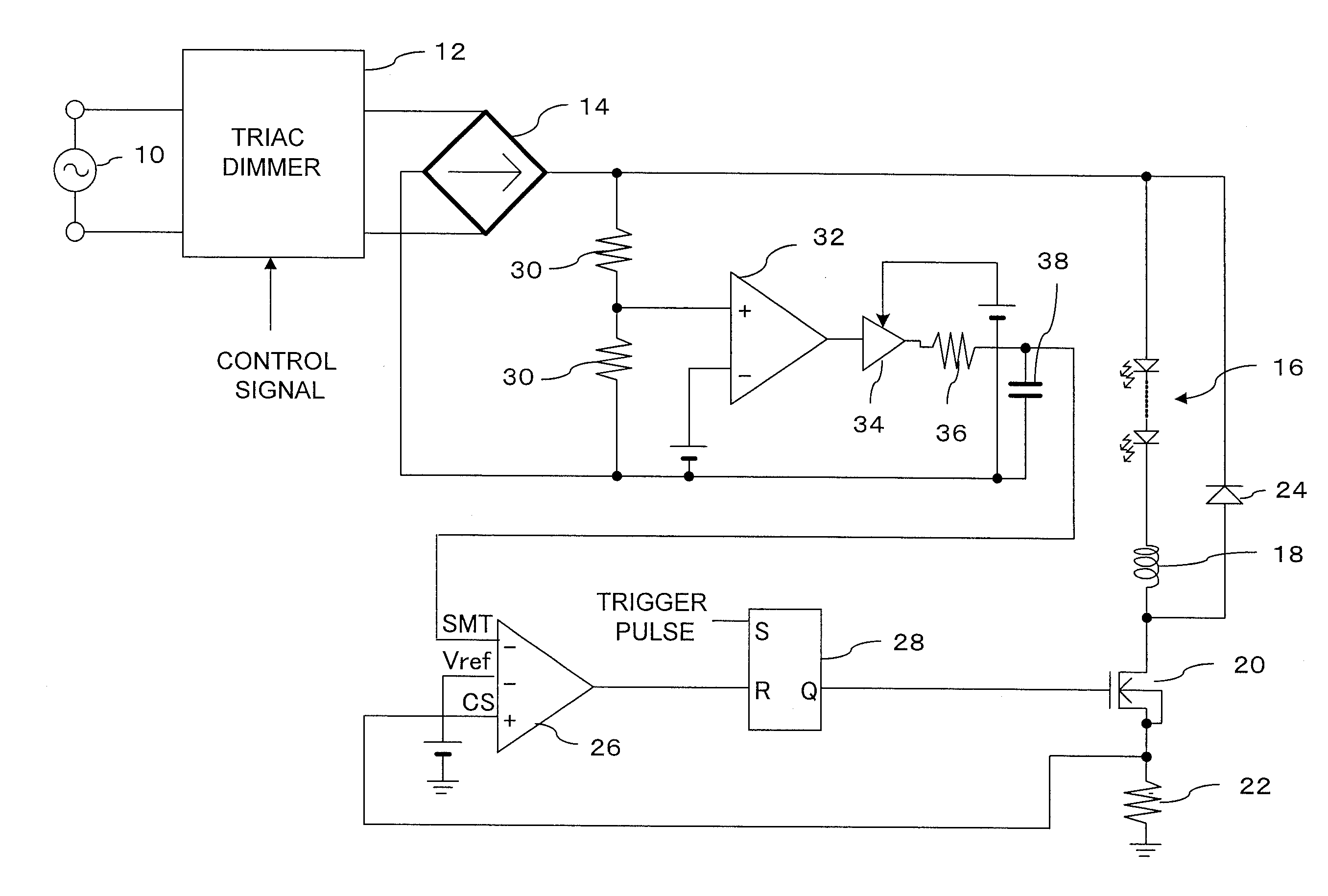
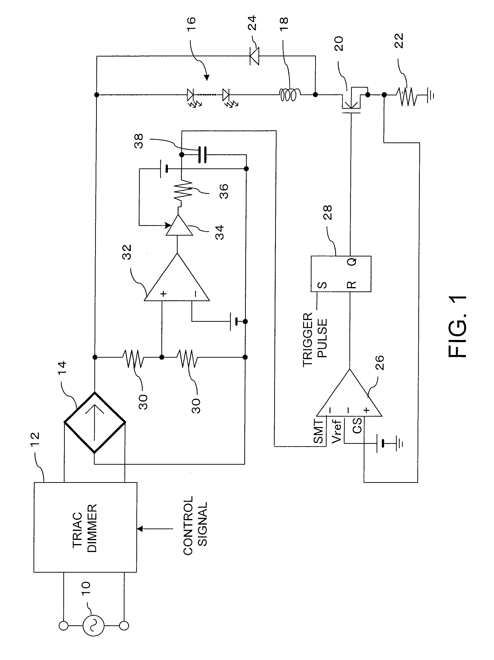
[0017]FIG. 1 shows a configuration of an embodiment. An AC power source 10, for example, is a 100 V, 50 Hz (or 60 Hz) commercial power source available from a household outlet. The AC power from the AC power source 10 is supplied to a TRIAC dimmer 12. The TRIAC dimmer 12 removes part of the AC waveform from the AC power source 10 to generate a TRIAC pulse in accordance with a separately supplied control signal for the supplied power. For example, if the control signal is for setting the power to 50%, 50% of the AC waveform of one period is cut. In this case, out of one period of the AC waveform, cutting 1° to 90° and 180° to 270° sets the power to 50%. This is easily accomplished, for example, by a gate circuit.

[0018]The TRIAC pulse from the TRIAC dimmer 12 is supplied to a full wave rectifier 14. The full wave rectifier 14 uses a rectifying device, such as a ...


PUM


Abstract

A TRIAC dimmer gates an AC waveform from an AC power source in proportion to a control signal and outputs a TRIAC pulse having part of the waveform missing. The TRIAC pulse is rectified and is applied to an LED array and the drive current flowing to the LED array is detected at a current detection resistor. The drive current value and a predetermined value are compared at a comparator and in accordance with the comparison result thereof the control transistor is turned off. Then, the TRIAC pulse is converted to a DC voltage signal and in accordance with the obtained DC voltage signal the drive current value or the predetermined value input by the comparator are changed. Furthermore, instead of the TRIAC pulse, a PWM pulse supplied from an external source may also be utilized.

Description

CROSS-REFERENCE TO RELATED APPLICATION(S)[0001]The present application claims priority pursuant to 35 U.S.C. §119(a) to Japanese Patent Application No. 2011-073265, filed on Mar. 29, 2011, the contents of which is hereby incorporated by reference in its entirety.BACKGROUND[0002]1. Field of the Invention[0003]One or more embodiments of the present invention relate to a light emitting diode (LED) dimmer circuit for dimming, in accordance with a control signal, an LED illuminated by an alternating current (AC) power source.[0004]2. Background Art[0005]Heretofore, triode for alternating current (TRIAC) dimmers were used for adjusting the brightness of illuminating lamps. The TRIAC dimmer gates the AC waveform, such as from a common commercial 100V AC power source, at a proportion according to a control signal, which is input such as from a switch, and outputs a TRIAC pulse having part of the waveform missing. Therefore, by directly applying the TRIAC pulse to a light bulb, for example, ...

Claims


Application Information

Patent Timeline
Patent Type & Authority Applications(United States)
IPC IPC(8): H05B37/02
CPCH05B33/0851H05B33/0818H05B33/0815H05B45/10H05B45/3725H05B45/48H05B45/37
Inventor KAWAI, SHUHEIGOTO, TOMOYUKIXU, FENG
Owner SEMICON COMPONENTS IND LLC
Learn More