
Fluid pressure booster and fluid pressure brake apparatus having the same

a technology of fluid pressure brake and fluid pressure booster, which is applied in the direction of fluid couplings, rotary clutches, braking systems, etc., can solve the problems of lowering deteriorating the operation feeling of the brake and the durability of the master cylinder cup, and reducing the precision of the control of the wheel cylinder pressure. , to achieve the effect of suppressing the deterioration of the control precision of the wheel cylinder pressur

Inactive Publication Date: 2012-10-04
ADVICS CO LTD
View PDF6 Cites 12 Cited by
  • Summary
  • Abstract
  • Description
  • Claims
  • Application Information

AI Technical Summary

Benefits of technology

[0018]Accordingly, an object of the present invention is to suppress the deterioration of the control precision of the wheel cylinder pressure, the pulsation influencing the durability of the cup of the master cylinder and the deterioration of the operation feeling of the brake, which are caused due to the pump back when the fluid pressure booster is used in combination with a reflux-type pressure adjusting unit (ABS unit or ESC unit).
[0020]The above fluid pressure booster may include a maximum reaction force regulation mechanism which allows the axial compression of the displacement absorption member when the fluid pressure of the boost chamber is lower than the fluid pressure of the auxiliary fluid pressure source and regulates an increase in an amount of the axial compression of the displacement absorption member when the fluid pressure of the boost chamber is equal to or higher than the fluid pressure of the auxiliary fluid pressure source.
[0027]According to the fluid pressure booster and the fluid pressure brake apparatus having the same, when the master piston of the master cylinder is applied with the pushing back force due to the pump back, the displacement absorption member is compressed. Hence, the piston displacement which is transferred from the master piston to the boost piston or the amount that the master piston itself is pushed back is decreased and the amount that the boost piston is pushed back by the master piston is also decreased, so that the increase of the boost pressure and the resultant increase of the master cylinder pressure are suppressed. As a result, the control precision of the wheel cylinder pressure is stabilized and the reliability of the ABS control or ESC control is improved.
[0028]Also, the increase of the boost pressure is suppressed, and therefore, the generation of the pulsation is suppressed and the deterioration of the operation feeling of the brake is also suppressed.

Problems solved by technology

However, since it is not possible to expect the assist by the negative force of the engine in a valve matic vehicle in which an intake valve lift amount is continuously varied to enable an intake value to function as a throttle valve, an HEV (hybrid electric vehicle), an EV (Electric Vehicle) and the like.
However, when the fluid pressure booster is adopted instead of the vacuum booster, the precision of the pressure adjustment is lowered due to the pump back, so that an operation feeling of the brake and the durability of a cup of the master cylinder are thus deteriorated.
Therefore, there would be caused the lowering of the control precision of the wheel cylinder pressure, which deteriorates the reliability of the ABS control and the like, the pulsation, which deteriorates the durability of the cup of the master cylinder and the like, the deterioration of the operation feeling of the brake and the like.
Accordingly, there would be also caused the lowering of the control reliability, the deterioration of the operation feeling and the like although the degrees thereof are less than those in the fluid pressure brake apparatus adopting the differential pressure control.

Method used


Image

  • Fluid pressure booster and fluid pressure brake apparatus having the same
  • Fluid pressure booster and fluid pressure brake apparatus having the same

Examples


Embodiment Construction

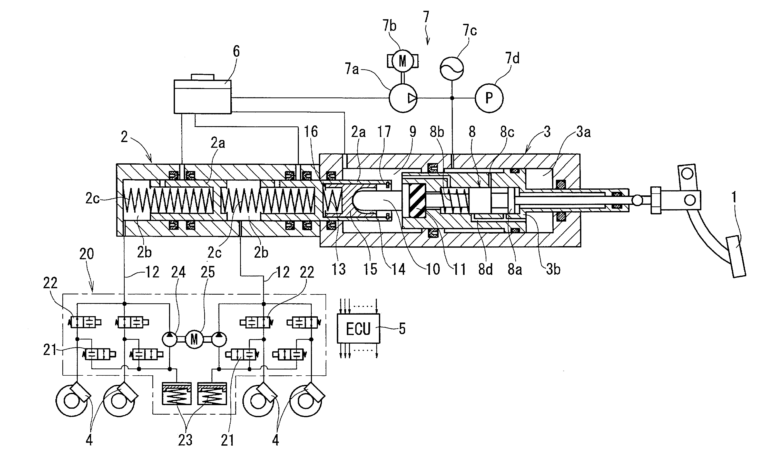
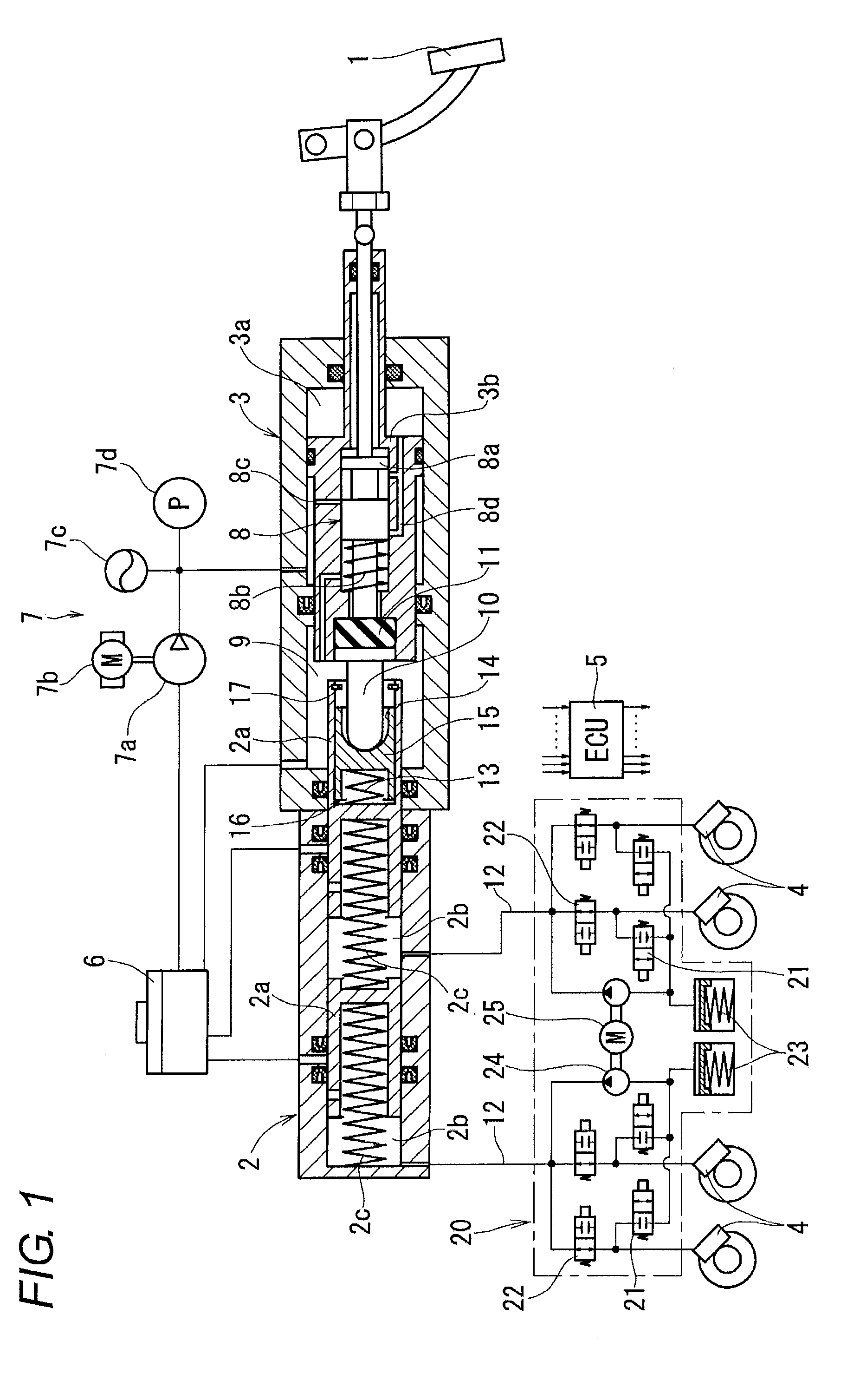
[0035]Hereinafter, an illustrative embodiment of a fluid pressure booster and a fluid pressure brake apparatus having the same is described with reference to FIG. 1.

[0036]A fluid pressure brake apparatus shown in FIG. 1 includes a brake operation member (brake pedal in FIG. 1) 1, a master cylinder 2, a fluid pressure booster 3, a wheel cylinder 4 which generates braking force by fluid pressure supplied from the master cylinder 2, a reflux-type pressure adjusting unit 20 and an electronic control unit 5. A reference numeral 6 indicates a reservoir which is provided as an auxiliary fluid source. A sensor or the like which transmits information, which indicates necessity of pressure decrease and pressure increase of the wheel cylinder 4, to the electronic control unit 5 is not shown in the FIGURE.

[0037]As an example of the master cylinder 2, a known tandem type master cylinder is shown which includes a return spring 2c pressing a master piston 2a to generate fluid pressure in a pressur...


PUM


Abstract

A fluid pressure booster and a fluid pressure brake apparatus having the same are provided. The fluid pressure booster includes an auxiliary fluid pressure source having a pump and a pressure accumulator, a pressure adjusting device which adjusts fluid pressure supplied from the auxiliary fluid pressure source to a value corresponding to an operating amount of a brake operation member by displacement of a spool valve and introduces the same into a boost chamber, a boost piston which receives the fluid pressure introduced into the boost chamber to generate assist force and operates a master piston of a master cylinder by assisted force, and a displacement absorption member which is provided at a position to which thrust force of the master piston is applied, and which is compressed in an axial direction when transfer power between the boost piston and the master piston exceeds a setting value.

Description

CROSS REFERENCE TO RELATED APPLICATIONS[0001]This application is based on and claims priority under 35 U.S.C.§119 to Japanese Patent Application 2011-075574, filed on Mar. 30, 2011, the entire content of which is incorporated herein by reference.BACKGROUND[0002]1. Field of the Invention[0003]The present invention relates to a fluid pressure booster which generates assist force corresponding to an operating amount of a brake operation member by using fluid pressure supplied from an auxiliary fluid pressure source and applies assisted force to a master cylinder, and a fluid pressure brake apparatus having the fluid pressure booster.[0004]2. Description of Related Art[0005]For example, U.S. Pat. No. 4,548,037 B discloses a basic technique of a fluid pressure booster which adjusts fluid pressure supplied from an auxiliary fluid pressure source having a power-operated pump and a pressure accumulator, to a value corresponding to an operating amount of a brake operation member with a press...

Claims


Application Information

Patent Timeline
IPC IPC(8): B60T13/128B60T13/16
CPCB60T8/4275B60T8/441B60T13/686B60T13/145B60T11/232
Inventor MIYATA, YOSHIHIRONOHIRA, SHIGEMITSU
Owner ADVICS CO LTD
Learn More