Magnetic resonance isolator

Active Publication Date: 2012-09-27
MURATA MFG CO LTD
View PDF0 Cites 0 Cited by
  • Summary
  • Abstract
  • Description
  • Claims
  • Application Information

AI Technical Summary

Benefits of technology

[0011]The operating principle of the magnetic resonance isolator according to the second preferred embodiment is preferably similar to that of the magnetic resonance isolator according to the first preferred embodiment. In the magnetic resonance isolator according to the second preferred embodiment, since the opposing conductor extending along the second main surface of the ferrite member in a direction perpendicular or substantially perpendicular to the main line is arranged so as to extend from the sub-line, a high-frequency magnetic field is confined within the ferrite member due to the opposing conductor such that leakage of the magnetic flux is reduced and the insertion loss is significantly reduced and prevented.
[0013]The operating principle of the magnetic resonance isolator according to the third preferred embodiment is preferably similar to that of the magnetic resonance isolator according to the first preferred embodiment. In the magnetic resonance isolator according to the third preferred embodiment, the ferrite member is preferably vertically or substantially vertically arranged on the mounting substrate in a state in which the ferrite member is sandwiched between a pair of permanent magnets respectively facing the first and second main surfaces of the ferrite member. Only a portion of the junction conductor parallel or substantially parallel to the thickness direction and provided on the ferrite member that is arranged vertically or substantially vertically on the mounting substrate faces a ground electrode, the impedance is increased and the insertion loss is reduced.

Problems solved by technology

This is problematic in view of recent trends in mobile communication apparatuses, i.e., reduction in size and increasing component mounting density.

Method used


Image

  • Magnetic resonance isolator
  • Magnetic resonance isolator
  • Magnetic resonance isolator

Examples


first preferred embodiment

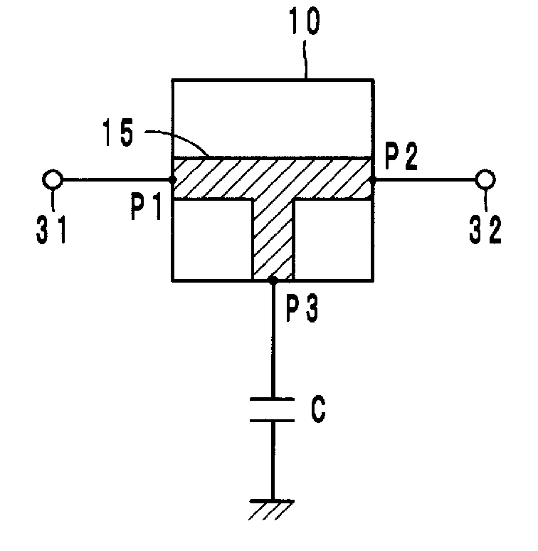
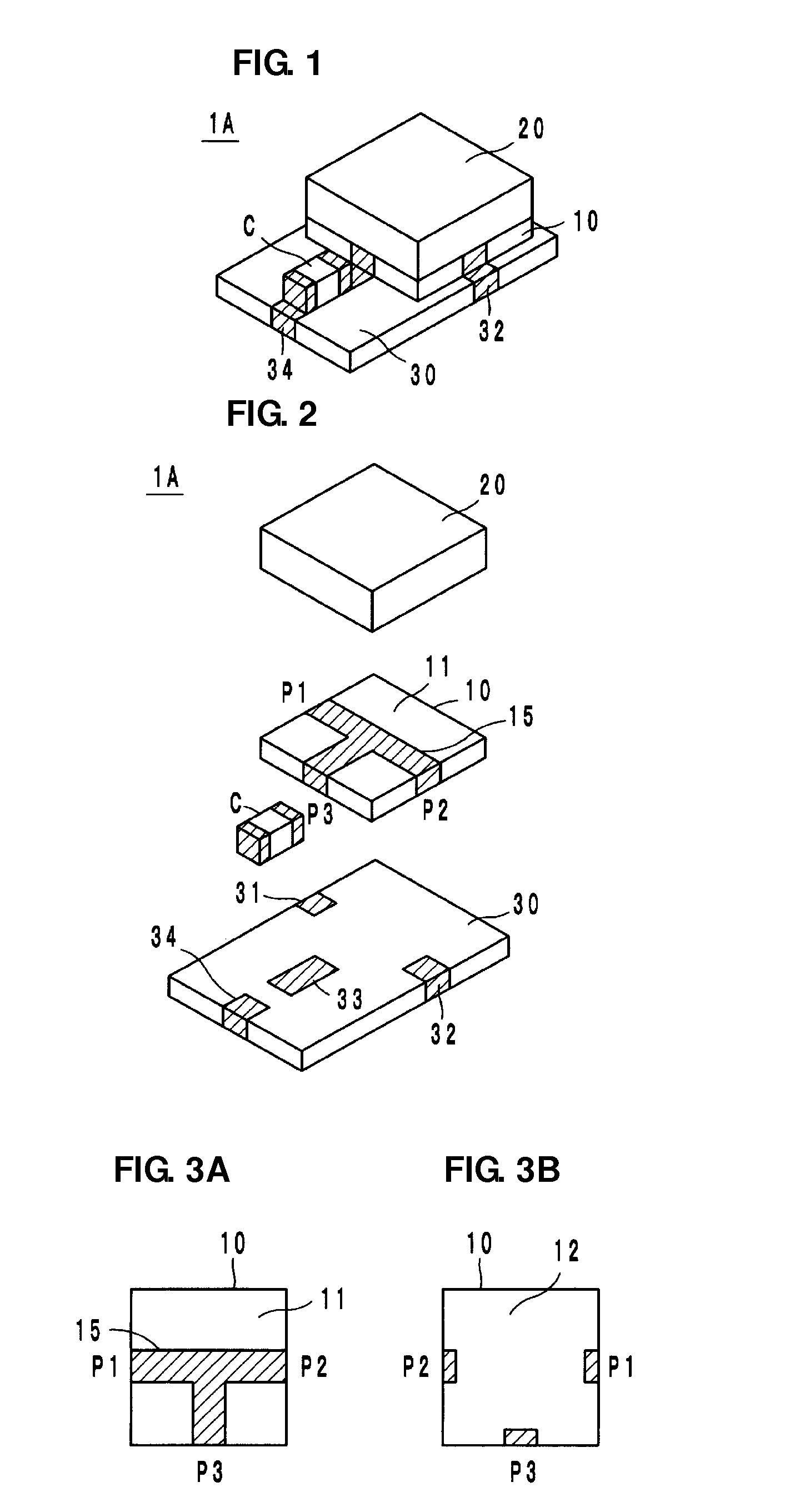
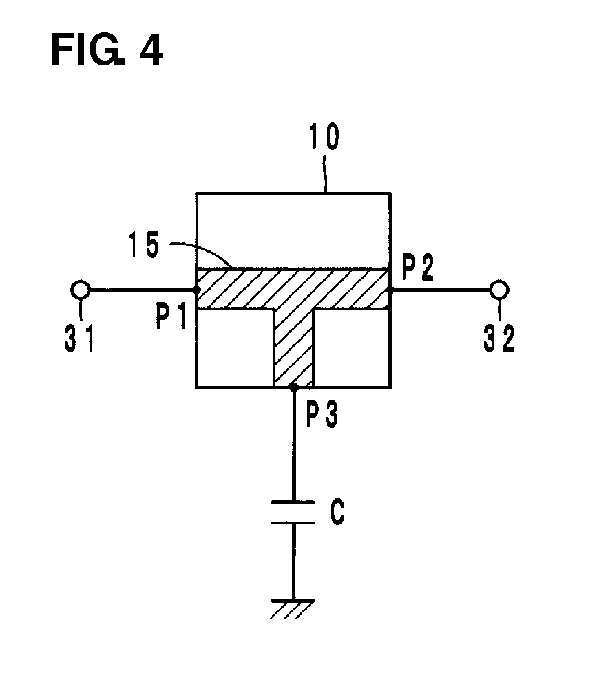
[0042]Referring to FIGS. 1 and 2, a magnetic resonance isolator 1A according to a first preferred embodiment of the present invention preferably includes a ferrite member 10, a T-shaped junction conductor 15 which is arranged on a first main surface 11 of the ferrite member 10 and which includes three ports P1, P2, and P3, a permanent magnet 20 that applies a direct current magnetic field to the ferrite member 10, a capacitor C as a reactance element, and a mounting substrate 30.

[0043]The junction conductor 15 is preferably a thin film formed by conductive metal evaporation or a thick film formed by applying conductive paste and baking. Referring to FIGS. 3A, 3B, and 4, a main line arranged between the first port P1 and the second port P2 facing each other in a line, among the three ports P1, P2, and P3 of the junction conductor 15, preferably has a length less than or equal to a quarter wavelength so as not to resonate. A sub-line branching from the main line on the first main surf...

second preferred embodiment

[0049]Referring to FIG. 8B, in a magnetic resonance isolator 1B according to a second preferred embodiment of the present invention, a ground conductor 16 is provided on a second main surface 12 of the ferrite member 10 and a relay terminal electrode 35 to be connected to the ground conductor 16 is provided on the mounting substrate 30. The rest of the configuration is preferably similar to that of the first preferred embodiment. Thus, the second preferred embodiment produces operations and advantages which are similar to those of the first preferred embodiment.

[0050]With regard to the magnetic resonance isolator 1B according to the second preferred embodiment, the input return loss is illustrated in FIG. 10A, the isolation is illustrated in FIG. 10B, the insertion loss is illustrated in FIG. 10C, and the output return loss is illustrated in FIG. 10D. The saturation magnetization is preferably about 100 mT and the capacitance of the capacitor C is preferably about 4 pF, for example....

third preferred embodiment

[0051]In a magnetic resonance isolator 1C according to a third preferred embodiment of the present invention, the end of the sub-line branching from the main line of the junction conductor 15 on the first main surface 11 preferably includes an opposing conductor 17 (refer to FIG. 13B) which extends along the second main surface 12 in a direction perpendicular or substantially perpendicular to the main line. The end of the opposing conductor 17 defines the third port P3, which is connected to the relay terminal electrode 33. The capacitor C is connected between the relay terminal electrode 33 and the ground electrode 34. In the third preferred embodiment, the rest of the configuration is preferably similar to that of the first preferred embodiment. Thus, the third preferred embodiment produces operations and advantages which are similar to those of the first preferred embodiment.

[0052]With regard to the magnetic resonance isolator 1C according to the third preferred embodiment, the i...


PUM


Abstract

A magnetic resonance isolator includes a ferrite member, a junction conductor that is arranged on the ferrite member and that includes a first port, a second port, and a third port, a permanent magnet that applies a direct current magnetic field to the ferrite member, a capacitor as a reactance element, and a mounting substrate. A main line arranged between the first port and the second port does not resonate, and an end of a sub-line branching from the main line defines the third port. The capacitor is connected to the third port and to the ground. The phase of a wave reflected from the sub-line is adjusted so as to be shifted by about 90 degrees at the intersection of the junction conductor.

Description

BACKGROUND OF THE INVENTION[0001]1. Field of the Invention[0002]The present invention relates to magnetic resonance isolators, and specifically to magnetic resonance isolators used in a microwave frequency band, for example.[0003]2. Description of the Related Art[0004]In general, an isolator has a characteristic of transmitting signals in a predetermined direction and not transmitting signals in the opposite direction, and is mounted in a transmitter circuit of a mobile communication apparatus, such as a cellular phone. Known examples of magnetic resonance isolators include isolators described in Japanese Unexamined Patent Application Publication No. 63-260201 and Japanese Unexamined Patent Application Publication No. 2001-326504. A magnetic resonance isolator utilizes a phenomenon in which, when high-frequency currents of equal amplitude whose phases differ by a quarter wavelength flow through two lines (with four ports) perpendicular to each other, a rotating magnetic field (circu...

Claims


Application Information

Patent Timeline
IPC IPC(8): H01P1/36
CPCH01P1/365
Inventor HASEGAWA, TAKASHI
Owner MURATA MFG CO LTD
Why Eureka
Try Eureka