
Systems and Methods for Protecting a Series Capacitor Bank

Active Publication Date: 2010-09-09
GENERAL ELECTRIC CO
View PDF6 Cites 4 Cited by
  • Summary
  • Abstract
  • Description
  • Claims
  • Application Information

AI Technical Summary

Benefits of technology

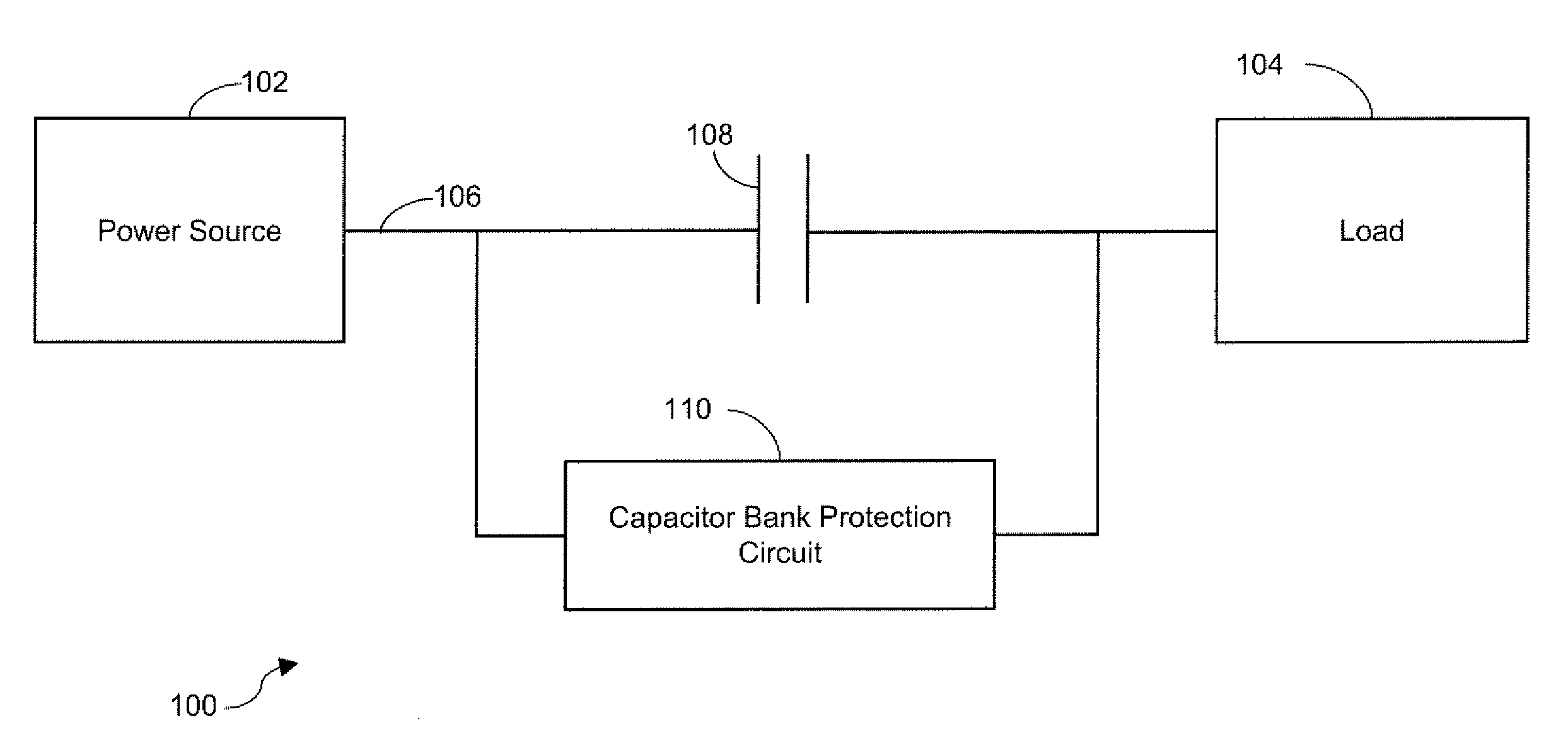
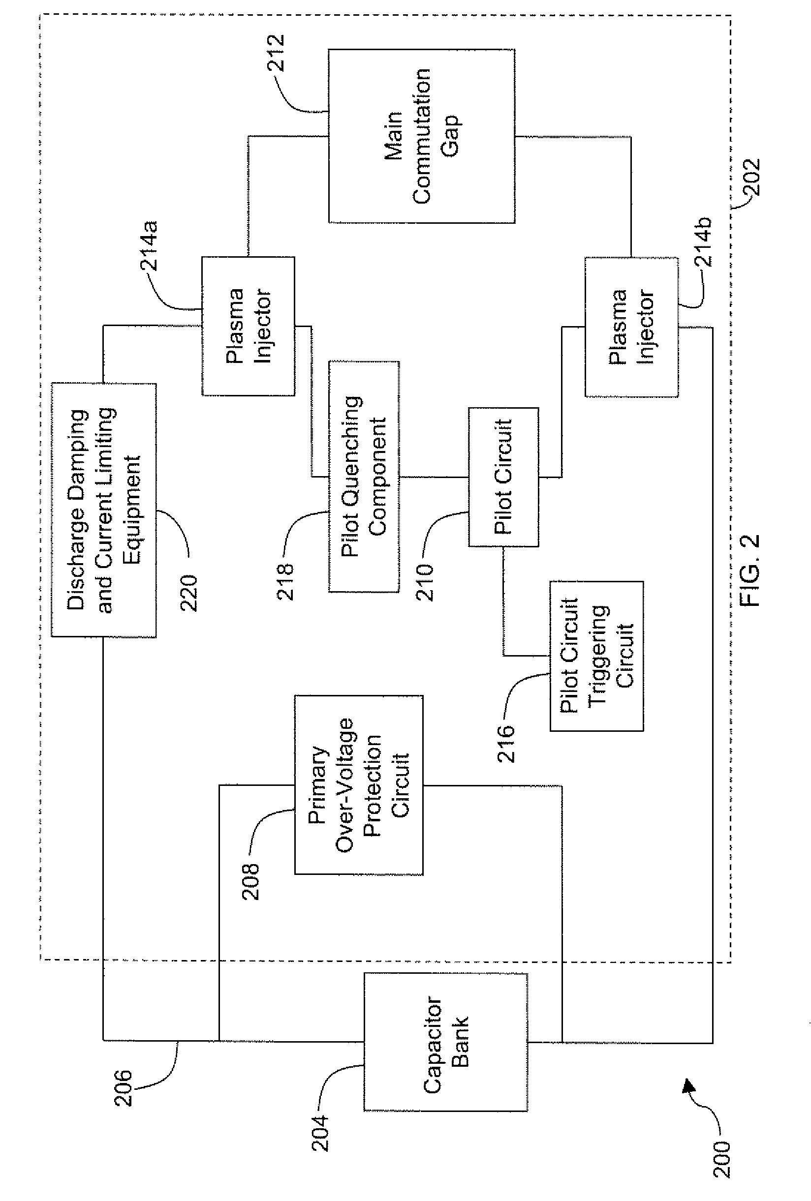
[0006]According to one exemplary embodiment of the invention, there is disclosed a capacitor protection circuit. The capacitor protection circuit may include a capacitor bank, a pilot circuit, and a main commutation gap. The pilot circuit and the main commutation gap may be provided in parallel electrical communication with the capacitor bank. Additionally, one or more plasma injectors may be provided in series electrical communication with the main commutation gap. The plasma injectors may be operable to provide partially or completely ionized plasma across the main commutation gap to make a conductive path across the main commutation gap.
[0007]According to another exemplary embodiment of the invention, there is disclosed a method for discharging a capacitor bank. The method may include a step of delivering a current through a pilot circuit, wherein the pilot circuit may be provided in parallel electrical communication with the capacitor bank. The method may further include a step of delivering the current through one or more plasma injectors that may be provided in series electrical communication with the pilot circuit. The plasma injectors may be operable to dielectr

Problems solved by technology

These techniques include use of a Metal Oxide Varistor, (MOV) which is susceptible to sustained overload conditions when the current and / or energy absorption exceeds its rated capacity.
This combination of requirements into just one component may be expensive in terms of cost, complexity of design, and unreliability.

Method used


Image

  • Systems and Methods for Protecting a Series Capacitor Bank
  • Systems and Methods for Protecting a Series Capacitor Bank
  • Systems and Methods for Protecting a Series Capacitor Bank

Examples


Embodiment Construction

[0014]Illustrative embodiments of the invention now will be described more fully hereinafter with reference to the accompanying drawings, in which some, but not all embodiments of the invention are shown. Indeed, the invention may be embodied in many different forms and should not be construed as limited to the embodiments set forth herein; rather, these embodiments are provided so that this disclosure will satisfy applicable legal requirements. Like numbers refer to like elements throughout.

[0015]Disclosed are systems and methods for protecting a capacitor bank and providing a capacitor bank protection circuit. The capacitor bank protection circuit may include a pilot circuit having high voltage capabilities and a main commutation gap having high voltage and high current carrying capabilities. The main commutation gap may be provided in a parallel connection with the pilot circuit. According to an embodiment of the invention, one or more plasma injectors may be provided in a series...


PUM


Abstract

Systems and methods for protecting a series capacitor bank are provided. According to one exemplary embodiment of the invention, there is disclosed a capacitor protection circuit. The capacitor protection circuit may include a capacitor bank, a pilot circuit and a main commutation gap. The pilot circuit and the main commutation gap may be provided in parallel electrical communication with the capacitor bank. Additionally, one or more plasma injectors may be provided in series electrical communication with the pilot circuit. The plasma injectors may be operable to provide partially or completely ionized plasma across the main commutation gap to make conductive the main commutation gap.

Description

FIELD OF THE INVENTION[0001]This invention relates generally to power transmission lines and more specifically relates to providing systems and methods for protecting a series capacitor bank.BACKGROUND OF THE INVENTION[0002]Series capacitor banks are used to enhance both the steady state and dynamic power transmission capacity of overhead power transmission lines by compensating the inductive reactance of the line.[0003]The use of a capacitor bank in series electrical connection (also interchangeably referred to herein as “electrical communication”) with the power transmission line makes the capacitor bank sensitive to the faults on the power transmission line. Various techniques are employed to protect the capacitor bank from an over-voltage condition. These techniques include use of a Metal Oxide Varistor, (MOV) which is susceptible to sustained overload conditions when the current and / or energy absorption exceeds its rated capacity. Traditionally, a non-conductive triggered (or t...

Claims


Application Information

Patent Timeline
IPC IPC(8): H02H7/16H02J7/00H02J3/00
CPCH02H7/16H02H7/008
Inventor ENGLISH, BRUCE EDWARDHART, CHRISTOPHER WILLIAMDATKA, PAUL JOSEPHBIRRELL, DAVID SCOTTMARTINS, DAVIDWILLARD, JR., ROBERT FRANKPOWERS, KENNETH ALANYOUNG, RICHARD ROBERT
Owner GENERAL ELECTRIC CO
Learn More