Thermal and chemical utilization of carbonaceous materials, in particular for emission-free generation of energy

Active Publication Date: 2012-09-20
RV LIZENZ
View PDF14 Cites 26 Cited by
  • Summary
  • Abstract
  • Description
  • Claims
  • Application Information

AI Technical Summary

Benefits of technology

[0059]A particular advantage of the invention is that the facility is independent of external conditions such as pressure, temperature, moisture, or all other external parameters. Since in facilities according to the invention the matter stream proceeds in a closed manner, the process is substantially independent of the ambient pressure.
[0060]A further substantial advantage of a facility according to the invention is that the closed system does not require a gas treatment. It is a further advantage that the formation and separation of liquid products from the synthesis gases in the third process stage inevitably leads to particles being separated out.
[0061]A particularly advantageous embodiment of a facility according to the invention comprises an energy installation that is arranged for generating electrical and / or mechanical energy and / or thermal energy, using the hydrocarbons and / or other products from the utilization installation as fuels. Advantageously, a drive device for generating electrical and / or mechanical energy from the fuels is provided in the energy installation, wherein said drive device obtains the energy necessary for operation from the oxidation of the fuels to an oxidation gas essentially consisting of carbon dioxide and water, and comprises a device for the compression and / or condensation of the oxidation gas.
[0062]The drive device can be designed as a fuel cell or as a heat engine. In a particularly advantageous variant, the drive device can be operated with pure oxygen as oxidizing agent.
[0063]In a further embodiment of a facility according to the invention, a heat exchanger is provided for cooling down the oxidation gas stream, upstream and / or downstream of the device for the compression and / or condensation of the oxidation gas.
[0064]In yet a further embodiment of a facility according to the invention, a device for condensation and / or separation of water from the oxidation gas is provided. This reduces, inter alia, the amount of the remaining residual gas.

Problems solved by technology

It has been known for some time that emissions, particularly carbon dioxide emissions, have very adverse effects on the climatic equilibrium of earth, and contribute greatly to manmade climatic heating.
When carbonaceous materials are used as fuels in conventional power plant installations, carbon dioxide is an unavoidable by-product of energy generation.
Separating out carbon dioxide from resultant combustion exhaust gases is generally not possible with a reasonable energetic and / or economic expenditure.
However, such systems are expensive and complicated.
Energy sources without carbon dioxide emissions such as, for example, solar power, wind power, water power, and nuclear energy have other problems.
Recent installations for using alternative energy sources such as wind power, solar energy and biomass have insufficient capacities for covering the steadily increasing energy demands.
In addition, weather-dependent energy sources frequently cannot ensure unconditionally the necessary output capacities.
In these processes some of the starting material is burned for energy generation, and so in the production of high-value end products large amounts of no longer utilizable carbon dioxide are produced.
Owing to manmade climatic warming, such inefficient processes are now becoming less and less acceptable.
A disadvantage of the known processes is the generation of emissions, the low efficiency, and the complicated structure and operation, particularly in installations in which coke is gasified in a fluidized stream or entrained flow.

Method used


Image

  • Thermal and chemical utilization of carbonaceous materials, in particular for emission-free generation of energy
  • Thermal and chemical utilization of carbonaceous materials, in particular for emission-free generation of energy
  • Thermal and chemical utilization of carbonaceous materials, in particular for emission-free generation of energy

Examples


Embodiment Construction

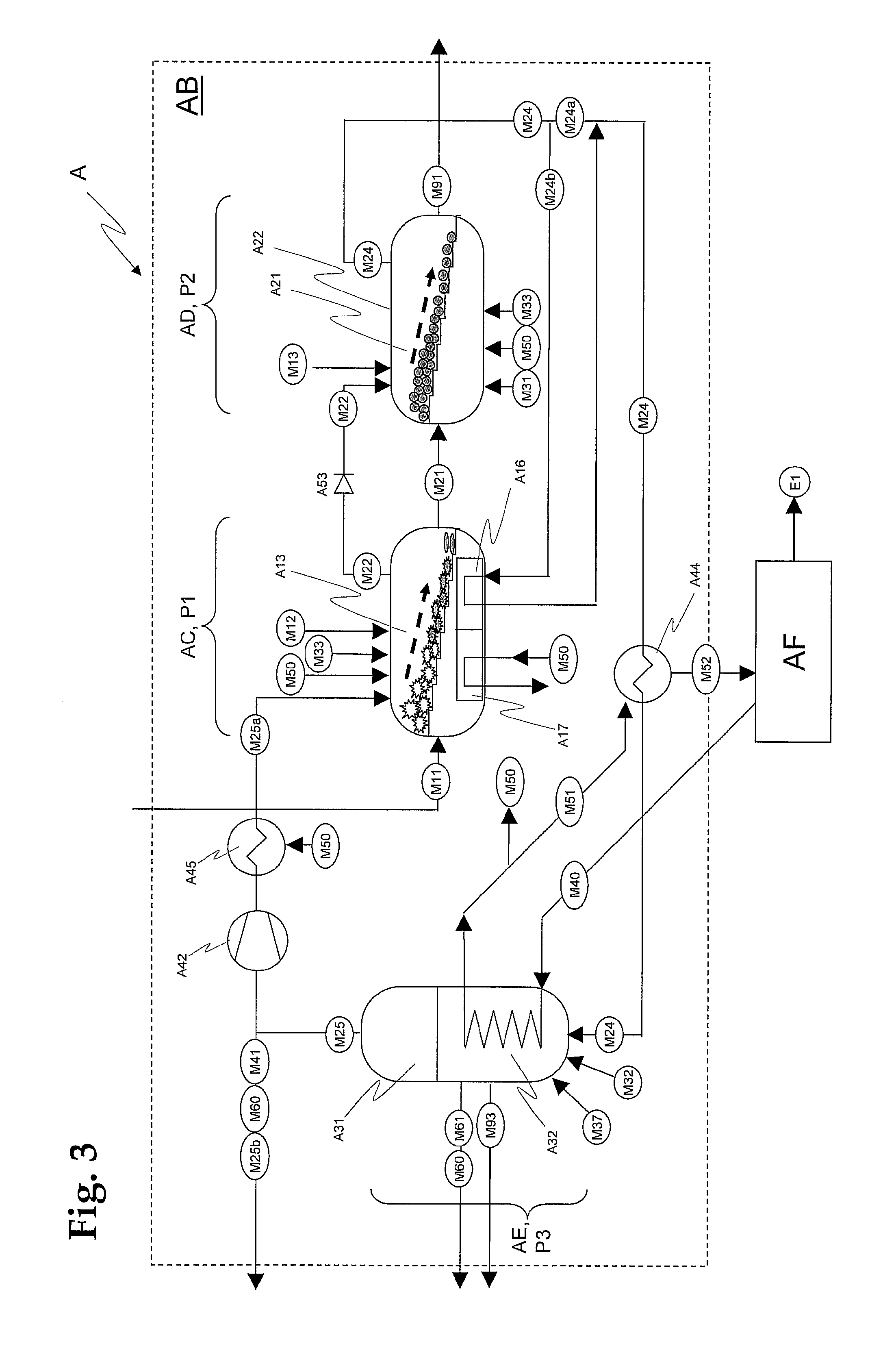
[0032]In a process according to the invention for the emission-free generation of energy and / or hydrocarbons and other products by utilization of carbonaceous materials, in a first process stage the carbonaceous materials are supplied and pyrolysed, wherein pyrolysis coke and pyrolysis gas are formed. In a second process stage, the pyrolysis coke from the first process stage is gasified, wherein synthesis gas is formed, and slag and other residues are removed. In a third process stage, the synthesis gas from the second process stage is converted into hydrocarbons and / or other solid, liquid and / or gaseous products, which are discharged. The three process stages form a closed cycle. Surplus gas from the third process stage is passed as recycle gas into the first process stage and / or the second process stage, and the pyrolysis gas of the first process stage is passed into the second process stage and / or the third process stage.

[0033]In an advantageous variant of this process, hydrogen ...


PUM

PropertyMeasurementUnit
Temperatureaaaaaaaaaa

Abstract

A process for the generation of energy and / or hydrocarbons and other products utilizing carbonaceous materials. In a first process stage (P1) the carbonaceous materials are supplied and are pyrolysed, wherein pyrolysis coke (M21) and pyrolysis gas (M22) are formed. In a second process stage (P2), the pyrolysis coke (M21) from the first process stage (P1) is gasified, wherein synthesis gas (M24) is formed, and slag and other residues (M91, M92, M93, M94) are removed. In a third process stage (P3), the synthesis gas (M24) from the second process stage (P2) is converted into hydrocarbons and / or other solid, liquid, and / or gaseous products (M60), which are discharged. The three process stages (P1, P2, P3) form a closed cycle. Surplus gas (M25) from the third process stage (P3) is passed as recycle gas into the first process stage (P1), and / or the second process stage (P2), and pyrolysis gas (M22) from the first process stage (P1) is passed into the second process stage (P2), and / or the third process stage (P3),

Description

TECHNICAL FIELD[0001]The invention relates to processes and facilities for emission-free generation of energy by thermal-chemical processing and utilization of solid, liquid and gaseous carbonaceous materials and mixtures, in particular of waste, biomass, coal and other heterogeneous materials. Further the invention relates to facilities for the generation of electrical and mechanical energy, and corresponding processes, as well as the manufacture of synthetic hydrocarbons and their use in such facilities.PRIOR ART[0002]It has been known for some time that emissions, particularly carbon dioxide emissions, have very adverse effects on the climatic equilibrium of earth, and contribute greatly to manmade climatic heating. Avoiding carbon dioxide emissions is therefore highly desirable, in particular in the generation of energy from carbonaceous materials, such as waste, biomass, and fossil fuels.[0003]When carbonaceous materials are used as fuels in conventional power plant installatio...

Claims


Application Information

Patent Timeline
IPC IPC(8): C07C27/00F28D7/02F02G3/00B01J19/00F01K23/06
CPCC10G2/30Y02E50/12C10J2300/094C10J2300/0959C10J2300/0966C10J2300/0969C10J2300/1606C10J2300/1659C10J2300/1665C10J2300/1671C10J2300/1675C10J2300/1693C10J2300/1807C10J2300/1823C10J2300/1846C10J2300/1884C10J2300/1892F01K13/00F02C3/28F23C2900/9901C10G2300/1011C10G2300/1022C10G2300/4037C10G2300/4081Y02T50/671Y02E20/12C10J3/66Y02P30/20Y02E20/32Y02E50/10C07C29/151C10G2/00F01K23/06C10J3/58C10J3/40C10J3/20
Inventor RUDLINGER, MIKAEL
Owner RV LIZENZ
Why Eureka
Try Eureka