
Imaging lens

Active Publication Date: 2012-09-13
TOKYO VISIONARY OPTICS CO LTD
View PDF1 Cites 9 Cited by
  • Summary
  • Abstract
  • Description
  • Claims
  • Application Information

AI Technical Summary

Benefits of technology

[0016]The conditional expression (1) indicates the conditions for shortening the length (thickness) of the imaging lens along the optical axis, and restricting the axial chromatic aberration, the off-axis chromatic aberration of magnification, the spherical aberration, and the field curvature within preferred ranges in a well-balanced manner.
[0023]If “da / L14” becomes smaller than the lower limit value “0.1,” on the other hand, the thickness of each lens becomes greater, and the workability of each lens becomes higher. However, it becomes difficult to restrict the respective aberrations within preferred ranges in a well-balanced manner.
[0030]If “f12 / f34” becomes smaller than the lower limit value “0.05” in the conditional expression (3), on the other hand, the composite focal length of the first lens and the second lens becomes short relative to the composite focal length of the third lens and the fourth lens, and the refractive power of the lens system is gathered in the first lens and the second lens. Accordingly, the imaging lens can be advantageously miniaturized, but it becomes difficult to restrict the spherical aberration and the coma aberration within preferred ranges in a well-balanced manner. Further, the incidence angles of off-axis light beams emitted from the imaging lens to imaging elements become larger, and it becomes difficult to restrain the incidence angles of light beams emitted from the imaging lens to the imaging elements within a predetermined range.
[0042]If the material of the first lens, the material of the third lens, and the material of the fourth lens are the same in the imaging lens having the above described configuration, only two kinds of materials are required in the formation of the imaging lens. Accordingly, the imaging lens production cost can be lowered. Further, the material of the first lens and the material of the fourth lens may be the same, and the material of the second lens and the material of the third lens may be the same. With this arrangement, the imaging lens production cost can also be lowered while chromatic aberrations are appropriately corrected.

Problems solved by technology

However, required optical performance has become higher every year in line with higher resolutions of imaging elements, and it has become difficult to realize high optical performance with appropriately-corrected aberrations and miniaturization at the same time depending on a two-lens or three-lens configuration.

Method used


Image

  • Imaging lens
  • Imaging lens
  • Imaging lens

Examples


numerical example 1

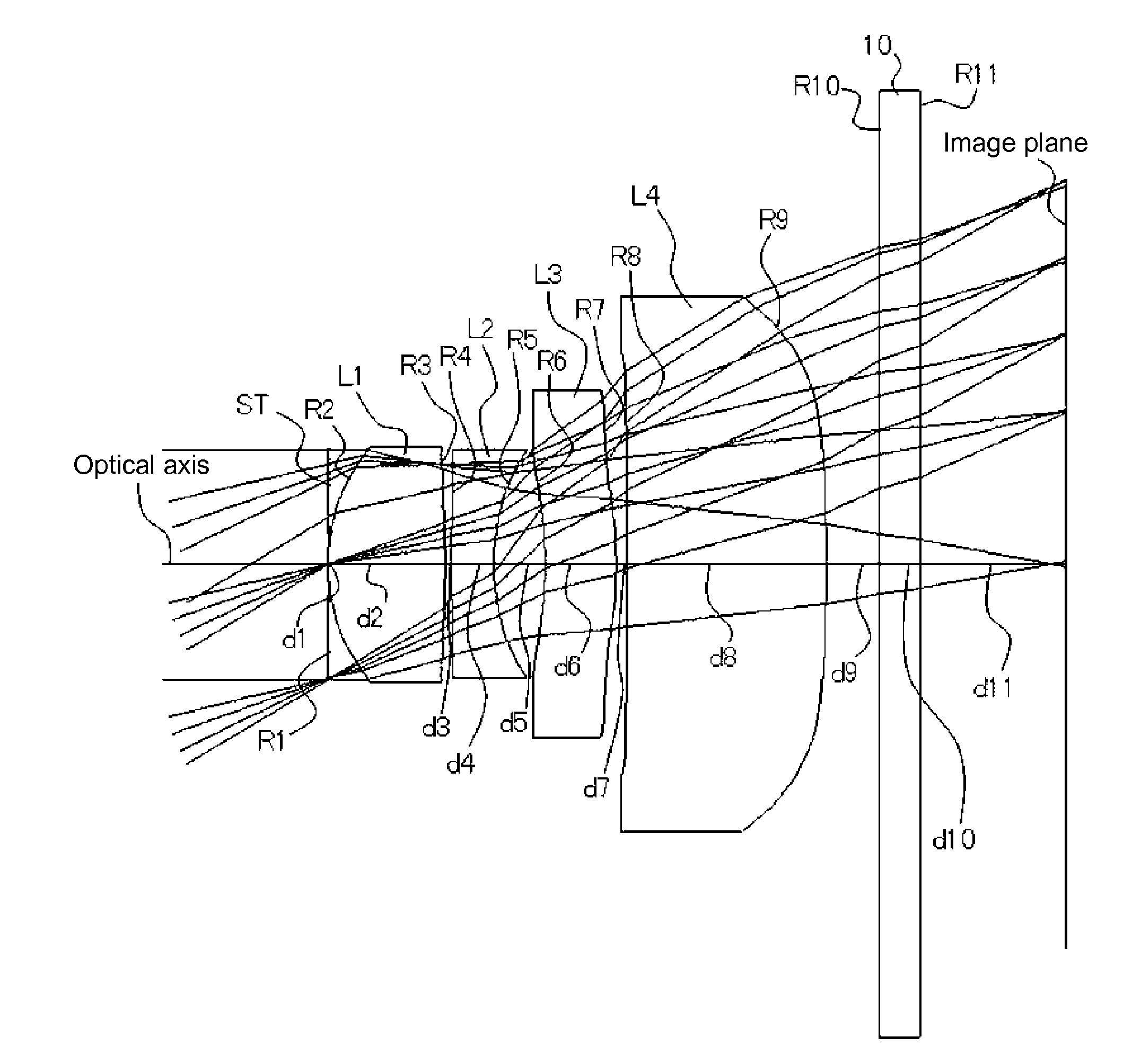
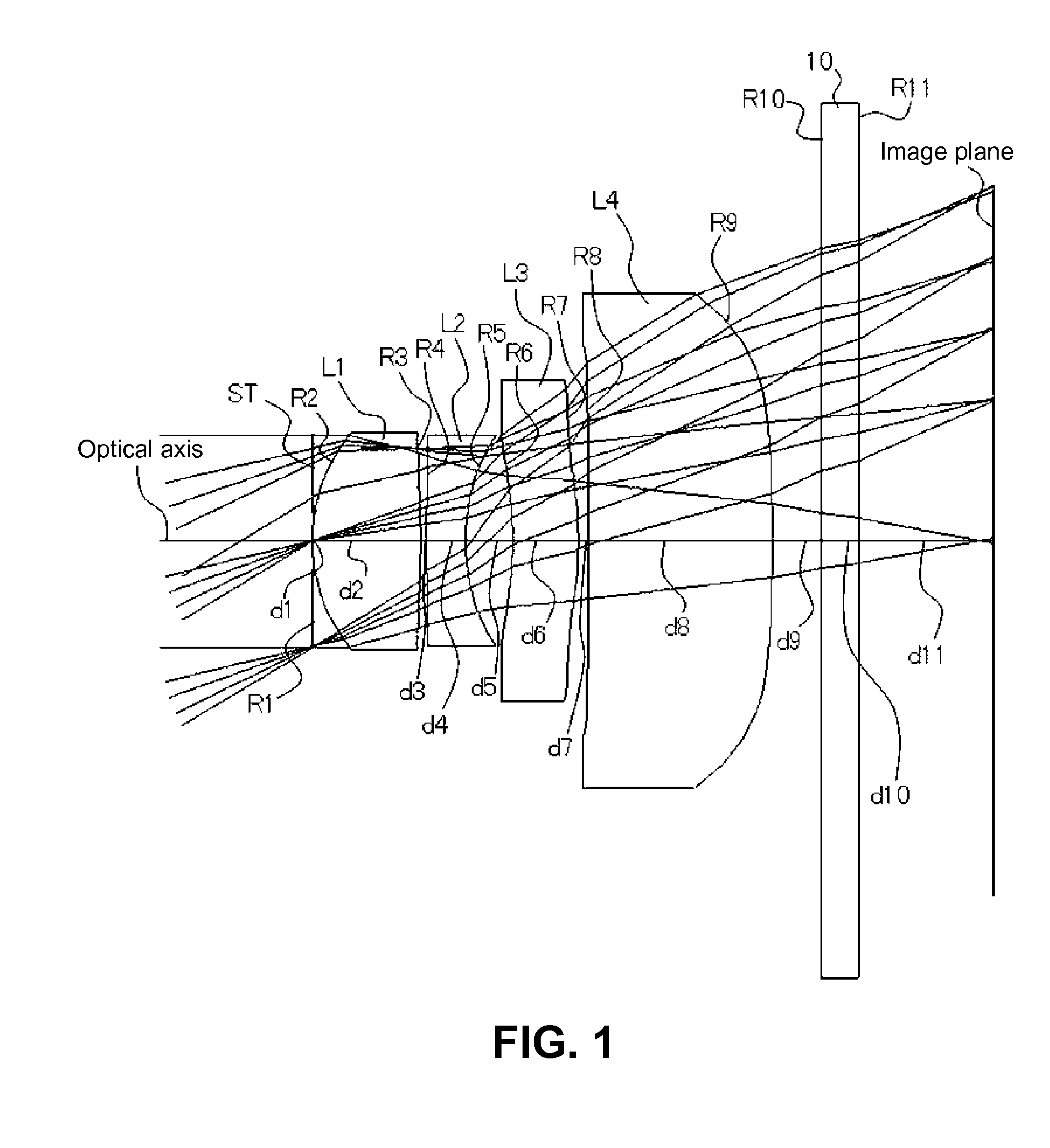
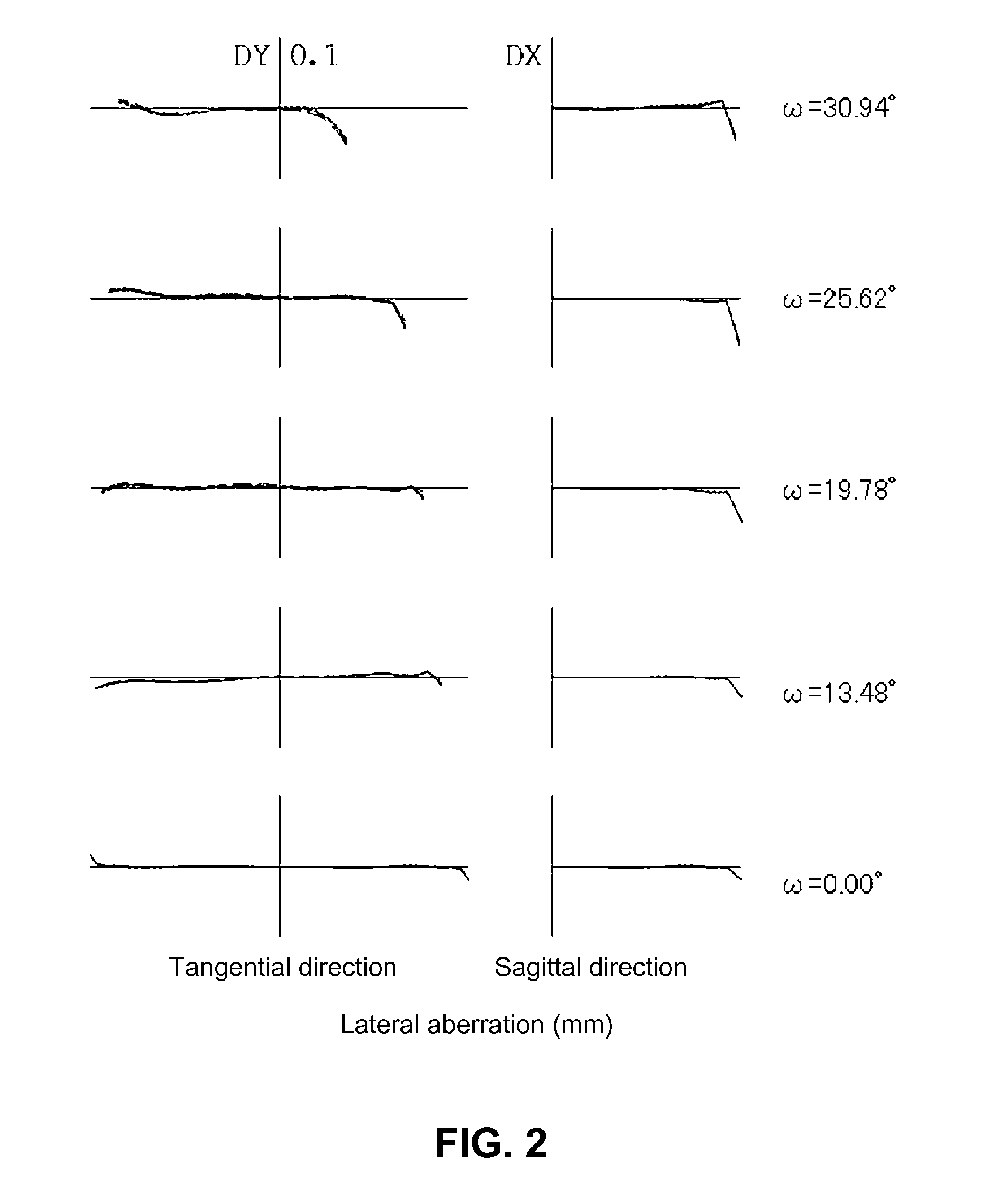
[0076]The basic lens data are as follows:

f = 4.792 mm, Fno = 2.800, ω = 30.94°Unit mmSurface dataSurface number iRdNdνd(Object)∞∞ 1 (stop)∞0.0000 2*1.4200.87001.5247056.2 (=νd1) 3*−7.2200.0500 4*16.1500.31601.6142026.0 (=νd2) 5*1.6600.3820 6*−3.0600.53001.5247056.2 (=νd3) 7*−3.1100.0800 8*80.0001.48901.5247056.2 (=νd4) 9*−24.0000.400010∞0.30001.5163364.1211∞1.0924(Image plane)∞f1 = 2.343f2 = −3.038f12 = 4.878f34 = 26.959da = 0.512L14 = 3.717Aspherical surface dataSecond surfacek = 7.124138E−01, A4 = −3.255467E−02, A6 = −3.345029E−02,A8 = 6.443935E−02, A10 = −8.410124E−02Third surfacek = 7.650370E+01, A4 = 6.319932E−03, A6 = 3.587828E−01,A8 = −3.390403E−01, A10 = −3.205488E−02Fourth surfacek = 0.000000, A4 = −7.977956E−02, A6 = 2.264327E−01,A8 = 1.561367E−01, A10 = −7.007116E−01Fifth surfacek = −7.378725E−01, A4 = −5.955688E−02, A6 = 3.026794E−01,A8 = −1.537807E−01, A10 = −8.573522E−02Sixth surfacek = 0.000000, A4 = 7.704037E−03, A6 = 9.406414E−02,A8 = −3.842276E−02, A10 = −2.456153E...

numerical example 2

[0081]The basic lens data are as follows:

f = 4.792 mm, Fno = 2.800, ω = 30.94°Unit mmSurface dataSurface number iRdNdνd(Object)∞∞ 1 (stop)∞0.0000 2*1.4120.85471.5247056.2 (=νd1) 3*−7.2120.0500 4*17.5130.36291.6142026.0 (=νd2) 5*1.6770.3525 6*−3.2890.58351.5247056.2 (=νd3) 7*−3.3260.1084 8*232.7371.39421.5247056.2 (=νd4) 9*−45.8630.400010∞0.30001.5163364.1211∞1.0252(Image plane)∞f1 = 2.330f2 = −3.046f12 = 4.724f34 = 44.905da = 0.511L14 = 3.706Aspherical surface dataSecond surfacek = 7.131351E−01, A4 = −3.329571E−02, A6 = −3.025131E−02,A8 = 6.952348E−02, A10 = −9.095330E−02Third surfacek = 7.004994E+01, A4 = 2.254029E−03, A6 = 3.700801E−01,A8 = −3.337891E−01, A10 = −7.588148E−02Fourth surfacek = 0.000000, A4 = −8.123492E−02, A6 = 2.096769E−01,A8 = 1.582786E−01, A10 = −6.600632E−01Fifth surfacek = −9.407782E−01, A4 = −6.543800E−02, A6 = 3.124348E−01,A8 = −1.747500E−01, A10 = −3.055272E−02Sixth surfacek = 0.000000, A4 = −7.554145E−03, A6 = 1.039733E−01,A8 = −5.658820E−03, A10 = −2.54429...

numerical example 3

[0084]The basic lens data are as follows:

f = 4.780 mm, Fno = 2.800, ω = 31.00°Unit mmSurface dataSurface number iRdNdνd(Object)∞∞ 1 (stop)∞0.0000 2*1.4110.86101.5247056.2 (=νd1) 3*−7.2400.0500 4*17.4160.36831.6142026.0 (=νd2) 5*1.6800.3500 6*−3.3080.59451.5247056.2 (=νd3) 7*−3.3640.1068 8*234.6981.37431.5247056.2 (=νd4) 9*−50.3690.400010∞0.30001.5163364.1211∞1.0069(Image plane)∞f1 = 2.330f2 = −3.054f12 = 4.688f34 = 49.155da = 0.507L14 = 3.705Aspherical surface dataSecond surfacek = 7.124973E−01, A4 = −3.340274E−02, A6 = −3.029348E−02,A8 = 6.979722E−02, A10 = −9.045849E−02Third surfacek = 6.983134E+01, A4 = 2.332465E−03, A6 = 3.712007E−01,A8 = −3.327910E−01, A10 = −7.740465E−02Fourth surfacek = 0.000000, A4 = −8.121136E−02, A6 = 2.083994E−01,A8 = 1.571260E−01, A10 = −6.573071E−01Fifth surfacek = −9.757836E−01, A4 = −6.636112E−02, A6 = 3.116588E−01,A8 = −1.762056E−01, A10 = −3.366125E−02Sixth surfacek = 0.000000, A4 = −8.748924E−03, A6 = 1.037168E−01,A8 = −3.758805E−03, A10 = −2.28558...


PUM


Abstract

An imaging lens, although compact, has satisfactorily corrected aberrations. The imaging lens is configured by disposing, in sequence from the object side, a stop (ST); a first lens (L1), which has a double convex shape near the optical axis; a meniscus-shaped negative second lens (L2) which has near the optical axis a convex surface facing the object side; a meniscus-shaped positive third lens (L3) which has near the optical axis a concave surface facing the object side; and a positive fourth lens (L4) which has a double convex shape near the optical axis. In the configuration, the refractive power of the first lens (L1) is greater than the refractive power of each of the second lens (L2), the third lens (L3), and the fourth lens (L4).

Description

CROSS-REFERENCE TO RELATED APPLICATIONS[0001]This is a continuation application of the prior PCT application PCT / JP2010 / 068445, filed on Oct. 20, 2010, pending, which claims priority from a Japanese patent application No. 2009-266973, filed on Nov. 25, 2009, the entire content of which is incorporated herein by reference.TECHNICAL FIELD AND BACKGROUND ART[0002]The present invention generally relates to an imaging lens that forms an image of an object on an imaging element such as a CCD sensor and a CMOS sensor. More particularly, the present invention relates to an imaging lens to be mounted on a relatively small camera, such as a cellular phone, a digital still camera, a portable information terminal, a security camera, an in-vehicle camera, and a network camera.[0003]In the recent years, cameras are included as a standard feature in most of cellular phone, so that the values added to those cellular phone are increased. The integration of the cellular phone and the digital still ca...

Claims


Application Information

Patent Timeline
IPC IPC(8): G02B9/34
CPCG02B9/34G02B13/18G02B13/004
Inventor KUBOTA, YOJIKUBOTA, KENICHIHIRANO, HITOSHIKURIHARA, ICHIROISE, YOSHIOFUKUDA, SUMIO
Owner TOKYO VISIONARY OPTICS CO LTD
Learn More