
Rotary hearth furnace

a hearth furnace and rotary technology, which is applied in the direction of muffle furnaces, furnace types, furnaces, etc., can solve the problems of affecting the effective use of radiant energy, the time in which oxygen-containing gas stays in the exhaust zone is maximized, and the energy cannot always be effectively utilized in the furnace, so as to achieve the effect of increasing the stirring effect, reducing the time in which oxygen-containing gas stays in the exhaust zone, and increasing the time in which oxygen-containing gas is

Inactive Publication Date: 2012-08-23
KOBE STEEL LTD
View PDF6 Cites 0 Cited by
  • Summary
  • Abstract
  • Description
  • Claims
  • Application Information

AI Technical Summary

Benefits of technology

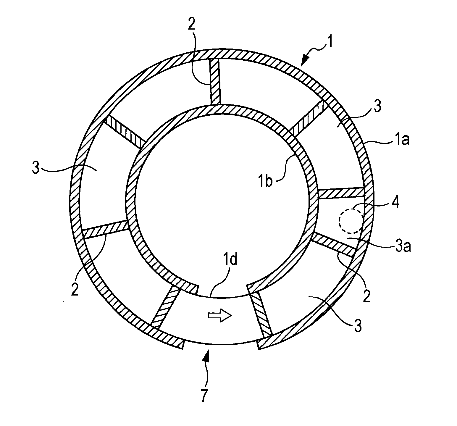
[0012]In the rotary hearth furnace according to the present invention, the center of the end portion of the exhaust gas duct is disposed at a position shifted toward the outer peripheral side or the inner peripheral side from the furnace width center of the exhaust zone. Accordingly, the flow of the exhaust gas in the furnace can be shifted toward the outer peripheral side or the inner peripheral side. Therefore, the exhaust gas is stirred in the furnace, and the combustion reaction between the combustible gas and the oxygen gas contained in the exhaust gas can be accelerated.
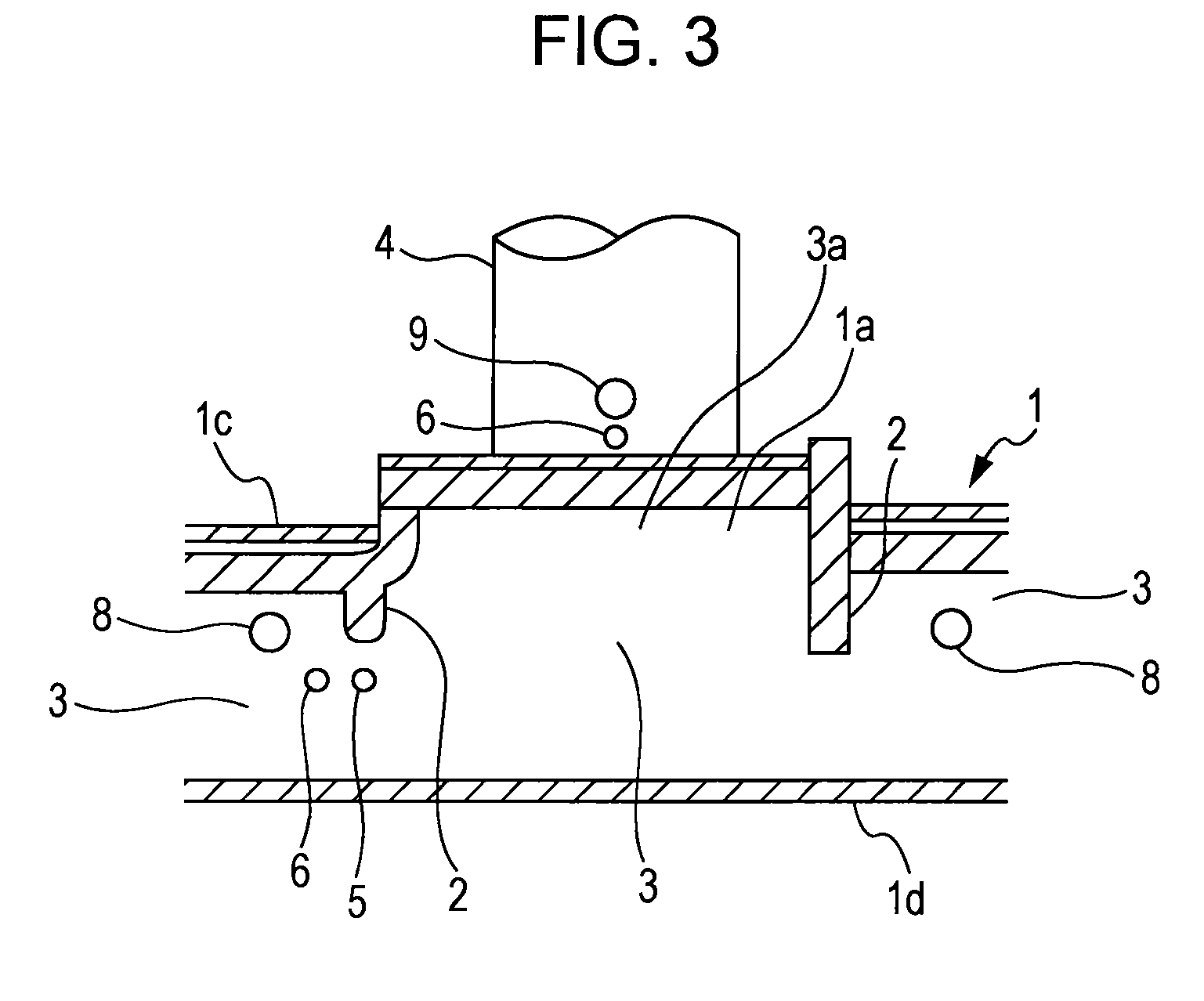
[0013]The oxygen-containing gas supply unit is disposed near the bottom edge of one of the vertical walls that divide the exhaust zone from other zone spaces. Preferably, the oxygen-containing gas supply unit is disposed near the hearth. In such a case, the stirring effect can be increased and the time in which the oxygen-containing gas stays in the exhaust zone can be maximized. Accordingly, combustion of the combustible gas contained in the exhaust gas can be further accelerated.
[0014]In addition, when the oxygen-containing gas supply unit is provided at the same side as the side at which the exhaust gas duct is attached, the stirring effect can be further increased by the oxygen-containing gas supplied from the oxygen-containing gas supply unit. Accordingly, the combustion efficiency can be further increased.
[0015]Of the vertical walls located at the ends of the exhaust zone in the circumferential direction, the oxygen-containing gas supply unit may be disposed near the bottom edge of the vertical wall at the end at which the flow ratio of the exhaust gas in the furnace is low. In this case, the uniform mixing time of the oxygen-containing gas can be reduced and the combustion can be reliably accelerated. When the oxygen-containing gas supply unit is disposed at a position near the rotary hearth, combustion is further accelerated, which contributes to improving the heat transfer to the object to be heated.
[0016]In addition, when a thermometer is disposed at each of an entrance section and an exit section of the exhaust zone, the amount of oxygen-containing gas supplied from the oxygen-containing gas supply unit can be adjusted. Accordingly, the amount of oxygen-containing gas that is unnecessarily supplied to the furnace can be reduced. If the amount of supply of the oxygen-containing gas is small, combustion will be insufficient and the temperature will be reduced. However, according to the above-described structure, the amount of supply of the oxygen-containing gas can be optimized and the combustion efficiency can be increased.
[0017]When the thermometer is disposed at the entrance section of the exhaust zone, the amount of oxygen-containing gas supplied to the exhaust gas upstream zone can be appropriately adjusted.

Problems solved by technology

Therefore, it takes a long time to burn the combustible gas.
In addition, since the combustion heat is generated at a position separated from the inside of the main body of the rotary hearth furnace, the energy cannot always be effectively utilized in the furnace.
There is a possibility that this will adversely affect the effective use of the radiant energy, in which case the radiant energy cannot be supplied to the object to be heated.

Method used


Image

  • Rotary hearth furnace
  • Rotary hearth furnace
  • Rotary hearth furnace

Examples


example

[0045]The present invention will now be described in more detail with reference to an example. However, the present invention is not limited to the following example. The present invention may be carried out with modifications as appropriate within the gist of the present invention, and such modifications are included in the technical scope of the present invention.

[0046]The example of the present invention will now be described. As illustrated in FIGS. 5 and 6, in this example, four oxygen-containing gas supply units (blowing nozzles) were provided at each of the other outer peripheral wall 1a and the inner peripheral wall 1b. Accordingly, eight oxygen-containing gas supply units were provided in total. One of these blowing nozzles was selected, and the opening degree thereof was set to 10 (fully opened). The opening degree of all of the other blowing nozzles was set to 1 (slightly opened) to protect the blowing nozzles from heat. In each case, the temperature at the position near ...


PUM


Abstract

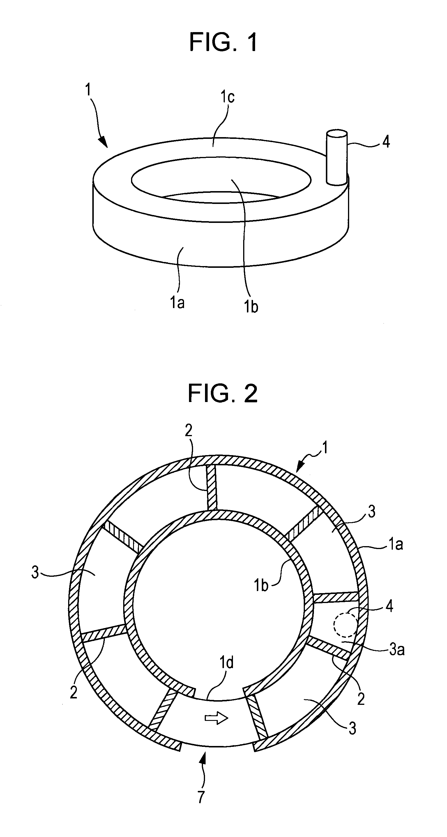
Provided is a rotary hearth furnace which can stir exhaust gas within a furnace, to efficiently burn flammable gas within the exhaust gas and to efficiently heat an object to be heated, and which can contribute to reduction of specific energy consumption and improvement of productivity. A rotary hearth furnace (1) has therein a series of zone spaces (3) which are divided by vertical walls (2) hanging from a ceiling (1c). Among the zone spaces (3), the zone space to which an exhaust gas duct (4) is attached is constructed as an exhaust zone (3a). An oxygen-containing gas supply unit (5) is provided in the vicinity of the lower edge of the vertical wall (2) which divides the exhaust zone (3a) from the other zone spaces (3). Further, the exhaust gas duct (4) is disposed on the outer periphery side or the inner periphery side from the center of the width of the zone space (3).

Description

TECHNICAL FIELD[0001]The present invention relates to rotary hearth furnaces in which dust generated in steel mills or the like, iron ore, etc., are used as raw materials. More specifically, the present invention relates to a rotary hearth furnace capable of efficiently burning combustible gas generated from agglomerates with a carbonaceous material (hereinafter referred to as an object to be heated) supplied to the furnace and fuel fed into the furnace.BACKGROUND ART[0002]Recently, a production method using a rotary hearth furnace has been attracting attention. In this production method, reduced iron is produced by supplying an object to be heated to the furnace and heating the object. The object to be heated is obtained by mixing iron ore, steel mill dust, etc., with a powdered carbonaceous material and agglomerating the mixture. During the reduction process, zinc and lead contained in the heated object are reduced and vaporized so that zinc, lead, etc., are separated and collecte...

Claims


Application Information

Patent Timeline
IPC IPC(8): F27B9/16F27D19/00F27B5/16
CPCF27B9/3005F27B9/16
Inventor TATEISHI, MASATAKATSUTSUMI, HIROFUMIMIYAKAWA, YUTAKAYASO, TADASHI
Owner KOBE STEEL LTD
Learn More