
Trench mosfet with trenched floating gates in termination

a technology of mosfet and termination gate, which is applied in the field of cell structure, device configuration and fabrication process of power semiconductor devices, can solve the problems of encountering technical problems in the structure of trench metal-oxide-semiconductor-field-effect-transistors (mosfets) having trenched floating gates as termination in the prior ar

Active Publication Date: 2012-08-23
FORCE MOS TECH CO LTD
View PDF3 Cites 21 Cited by
  • Summary
  • Abstract
  • Description
  • Claims
  • Application Information

AI Technical Summary

Benefits of technology

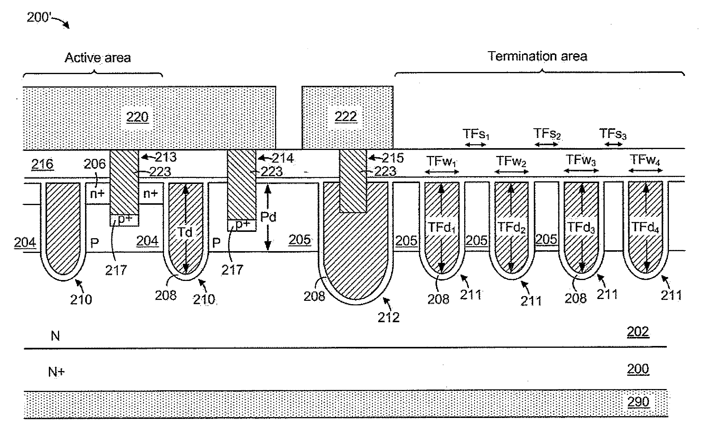
The present invention provides a trench MOSFET with multiple transistor cells in the active area and multiple trenched floating gates in the termination area. The trenched floating gates in the termination area have equal depth to the body junctions of the body regions surrounding them, and the source regions in the active area have higher doping concentration and greater source junction depth than the trenched floating gates. The trenched MOSFET also has low gate-to-drain charge Qgd, low source-to-drain charge Qsd, and low source-to-drain voltage. The trenched MOSFET further includes an equal potential ring and a trenched source-body contact for improved performance and stability.

Problems solved by technology

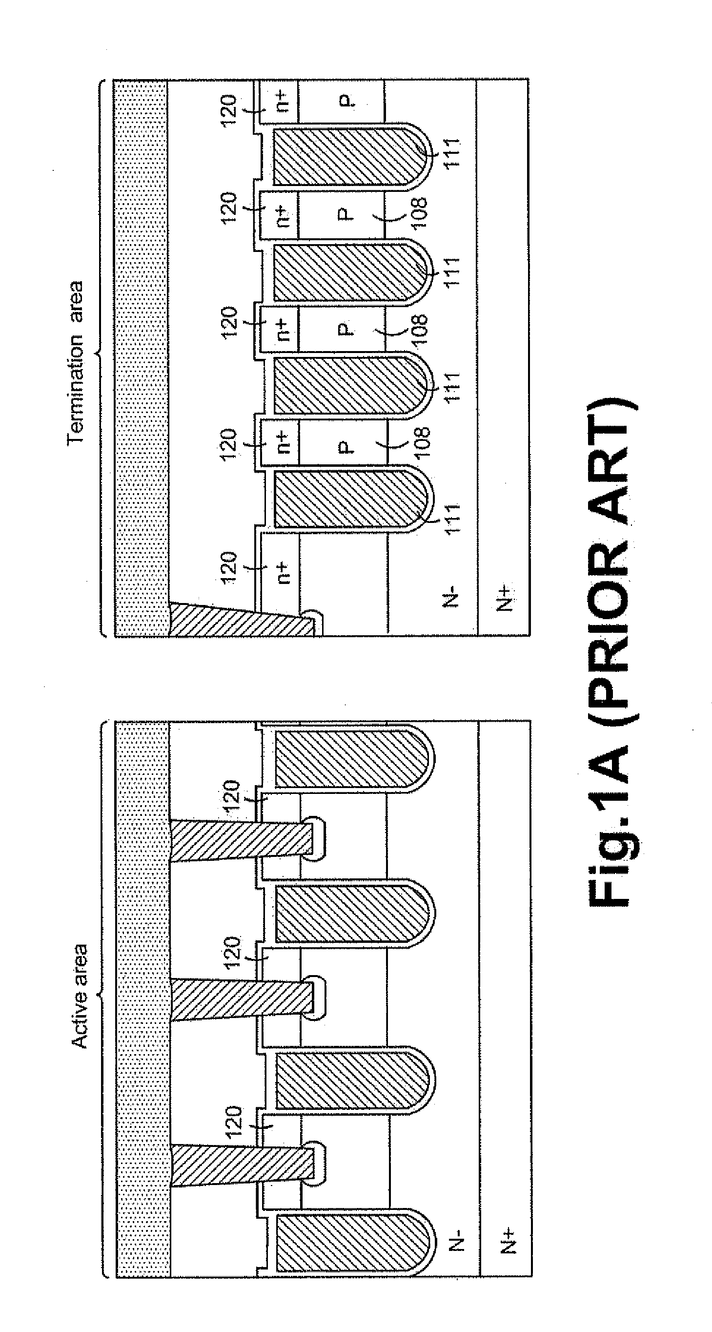
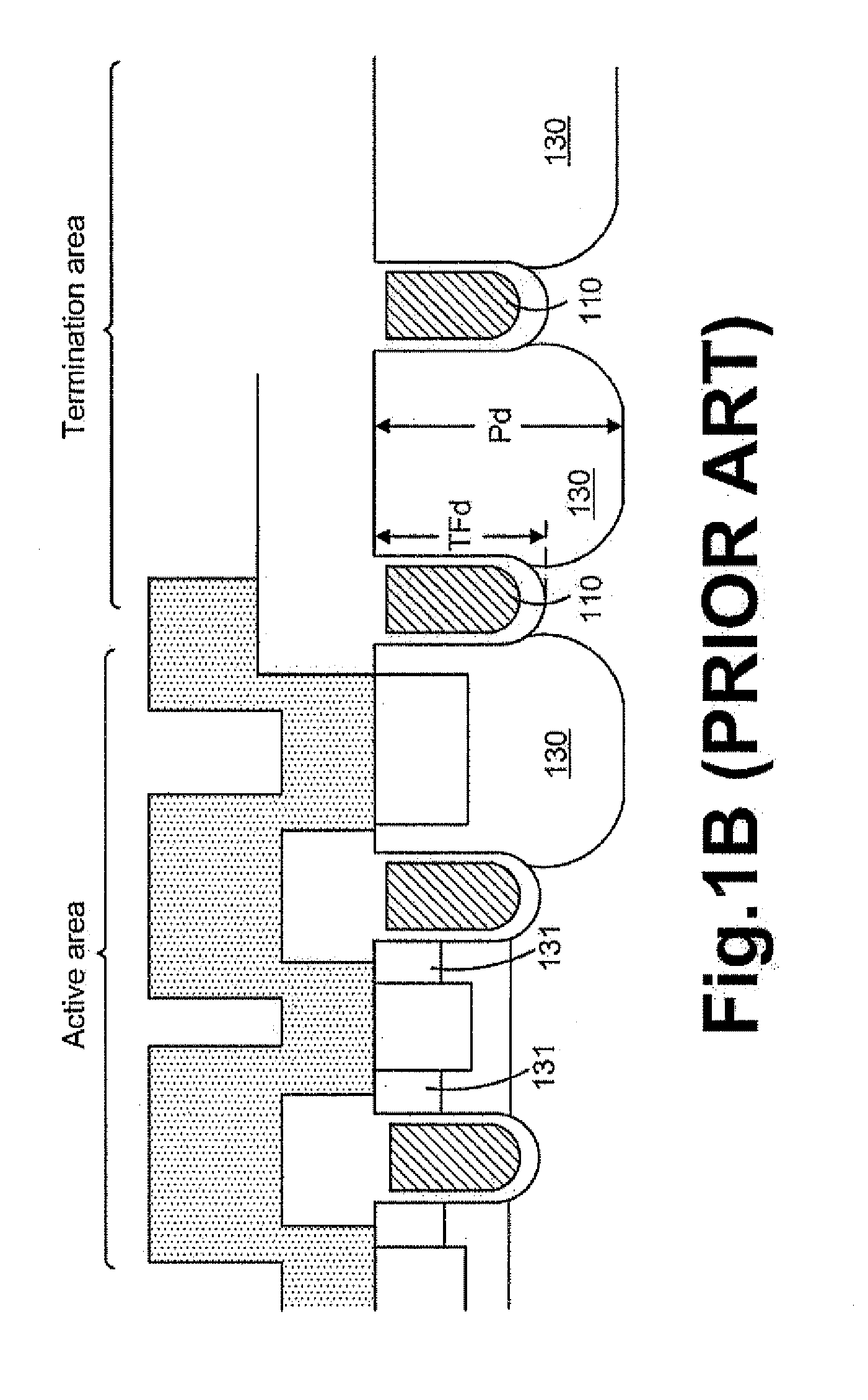
Typical structures of trench metal-oxide-semiconductor-field-effect-transistors (MOSFETs) having trenched floating gates as termination in prior arts are encountering technical problems.

Method used


Image

  • Trench mosfet with trenched floating gates in termination
  • Trench mosfet with trenched floating gates in termination
  • Trench mosfet with trenched floating gates in termination

Examples


Embodiment Construction

[0041]In the following Detailed Description, reference is made to the accompanying drawings, which forms a part thereof, and in which is shown by way of illustration specific embodiments in which the invention may be practiced. In this regard, directional terminology, such as “top”, “bottom”, “front”, “back”, etc., is used with reference to the orientation of the Figure(s) being described. Because components of embodiments can be positioned in a number of different orientations, the directional terminology is used for purpose of illustration and is in no way limiting. It is to be understood that other embodiments may be utilized and structural or logical changes may be make without departing from the scope of the present invention. The following detailed description, therefore, is not to be taken in a limiting sense, and the scope of the present invention is defined by the appended claims. It is to be understood that the features of the various exemplary embodiments described herein...


PUM


Abstract

A trench MOSFET comprising multiple trenched floating gates in termination area is disclosed. The trenched floating gates have trench depth equal to or deeper than body junction of body regions in active area. The trench MOSFET further comprise an EPR surrounding outside the multiple trenched floating gates in the termination area.

Description

CROSS REFERENCE TO RELATED APPLICATIONS[0001]This application is a Continuation-In-Part (CIP) of U.S. patent application Ser. No. 13 / 169,314 of the same inventor, filed on Jun. 27, 2011, entitled “trench MOSFET with trenched floating gates in termination”, which is a Continuation-In-Part of U.S. patent application Ser. No. 12 / 591,467 of the same inventor, filed on Nov. 20, 2009, now U.S. Pat. No. 7,989,887.FIELD OF THE INVENTION[0002]This invention relates generally to the cell structure, device configuration and fabrication process of power semiconductor devices. More particularly, this invention relates to a novel and improved cell structure, device configuration and improved process for fabricating trench metal-oxide-semiconductor-field-effect-transistors (MOSFETs) with trenched floating gates in termination to maintain a high breakdown voltage and to achieve a lower gate-to-drain charge Qgd and lower fabrication cost.BACKGROUND OF THE INVENTION[0003]Typical structures of trench ...

Claims


Application Information

Patent Timeline
Patent Type & Authority Applications(United States)
IPC IPC(8): H01L27/088
CPCH01L21/823481H01L21/823487H01L29/0619H01L29/0696H01L29/0878H01L29/407H01L29/1095H01L29/4236H01L29/7811H01L29/7813H01L29/423H01L29/456H01L29/0638H01L29/41766
Inventor HSIEH, FU-YUAN
Owner FORCE MOS TECH CO LTD
Learn More