Continuous flow reactor and method of using the same for treating nitrogen and phosphorus-containing wastewater
a technology of a continuous flow reactor and a coagulation method, which is applied in the direction of moving filter element filters, filtration separation, separation processes, etc., can solve the problems of large amount of emission, high pollutant concentration, and industrial wastewater, and achieve the effect of avoiding the accident of overflow, reducing the amount of pollution, and increasing the removal and recovery ratio of nitrogen and phosphorus
- Summary
- Abstract
- Description
- Claims
- Application Information
AI Technical Summary
Benefits of technology
Problems solved by technology
Method used
Image
Examples
example 1
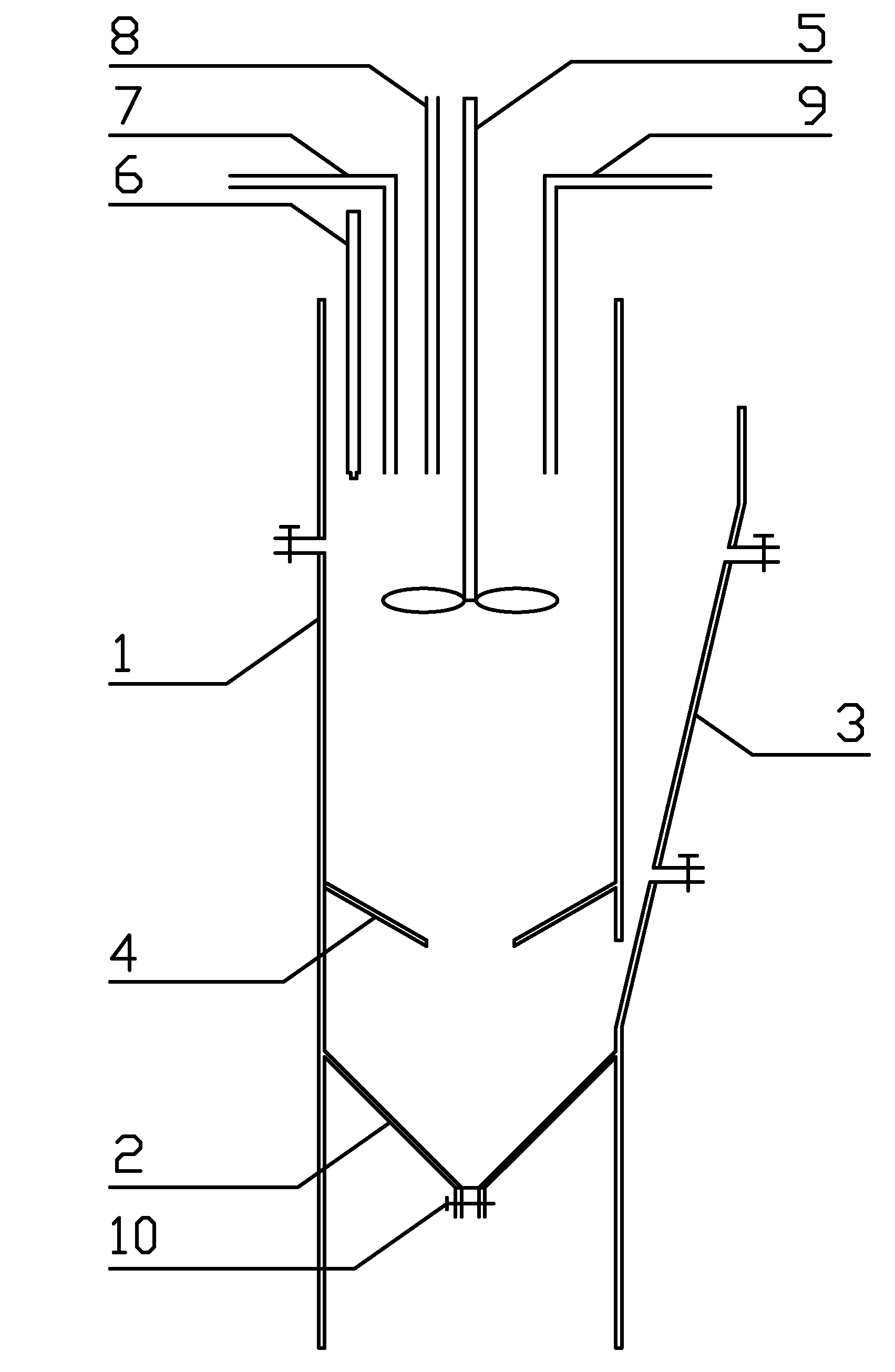
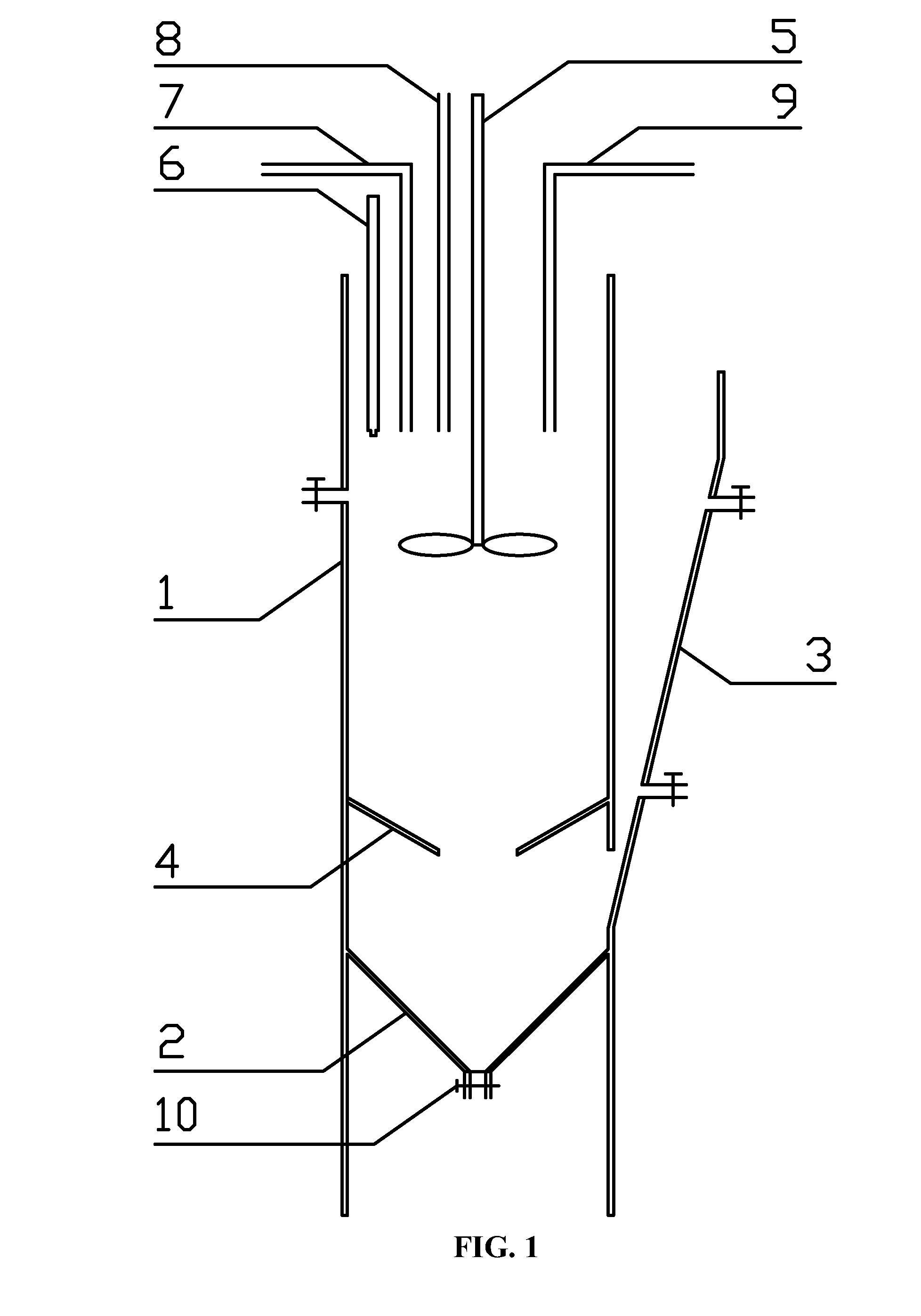
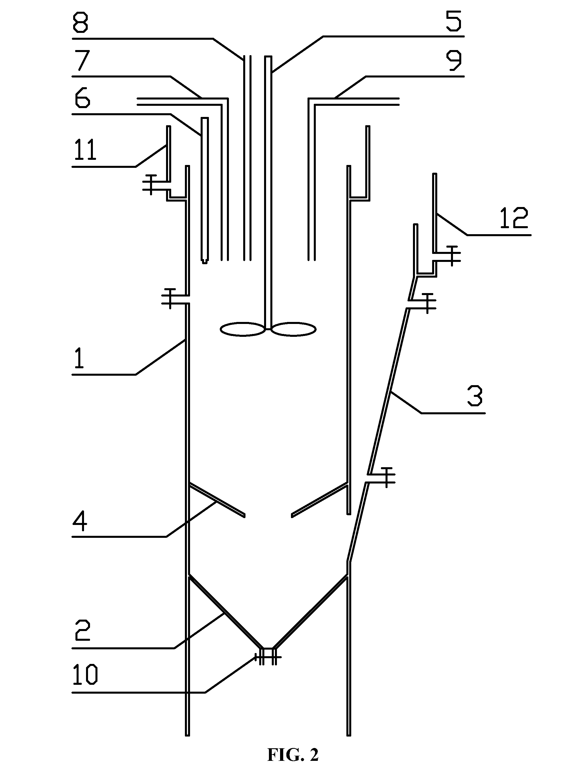
[0029]As shown in FIG. 2, a continues flow reactor for recycling high-concentration nitrogen and phosphorus wastewater by adopting the magnesium ammonium phosphate crystallization technology comprises a cylindrical coagulation crystallizer 1, a conical static settler 2, a wall-attached inclined plate settler 3, a funnel type protective baffle for static settling 4, a mechanical agitator 5, a dynamic pH monitor 6, a water inlet pipe 7, a magnesium source feed pipe 8, a pH regulator solution feed pipe 9, an MAP crystal discharge valve 10, a cylindrical influent protector 11 with a sawtooth slot, and a wall-attached effluent protector 12 with a sawtooth slot. The lower part of the cylindrical influent protector 11 with the sawtooth slot is connected with the upper part of the cylindrical coagulation crystallizer 1. The lower end surface of the cylindrical coagulation crystallizer 1 is connected with the upper end surface of the conical static settler 2. The funnel type protective baffl...
example 2
[0030]As shown in FIG. 2, a continues flow reactor for recycling high-concentration nitrogen and phosphorus wastewater is the same as that in Example 1 except that the overall volume of the reactor is 2.5 L, the ratio of height to diameter of the cylindrical coagulation crystallizer 1 is 3:1, and the distance from the joint between the funnel type protective baffle for static settling 4 and the cylindrical coagulation crystallizer 1 to the bottom of the cylindrical coagulation crystallizer 1 is ⅓ of height of the cylindrical coagulation crystallizer 1; the height of the wall-attached inclined plate settler 3 is ¾ of that of the cylindrical coagulation crystallizer 1, and an acute angle formed between an inclined plate of the wall-attached inclined plate settler 3 and the wall surface of the cylindrical coagulation crystallizer 1 is 30°; an acute angle formed between the funnel type protective baffle for static settling 4 and the wall surface of the cylindrical coagulation crystalliz...
example 3
[0031]A method of removing and recycling nitrogen and phosphorus in wastewater comprises the following steps. 1) Starting stage of the reactor: after the mol ratio of NH4+—N and PO43−—P is adjusted to 1.25:1, the wastewater comprising NH4+—N and PO43−—P is introduced into the cylindrical coagulation crystallizer 1, after the sewage accounts for ⅚ of volume of the cylindrical coagulation crystallizer 1, a water-intake peristaltic pump is adjusted to ensure the water inflow is 1 L / h, meanwhile, the mechanical agitator 5 is opened, and the rotational speed of the mechanical agitator 5 is 60 rpm, then the magnesium source is added to the cylindrical coagulation crystallizer 1, and the concentration of the solution containing Mg2+ and the flow rate of the feed pipe are adjusted, so that the mol ratio of Mg2+ and NH4+ in the influent in the reactor is 1:1. The pH regulator solution feed pipe 9 is opened to ensure the pH value of the reaction liquid to remain 8.5. 2) Stabilization stage of...
PUM
| Property | Measurement | Unit |
|---|---|---|
| Fraction | aaaaa | aaaaa |
| Volumetric flow rate | aaaaa | aaaaa |
| Angular velocity | aaaaa | aaaaa |
Abstract
Description
Claims
Application Information
 - R&D
- Intellectual Property
- Life Sciences
- Materials
- Tech Scout
- Unparalleled Data Quality
- Higher Quality Content
- 60% Fewer Hallucinations
Browse by: Latest US Patents, China's latest patents, Technical Efficacy Thesaurus, Application Domain, Technology Topic, Popular Technical Reports.
© 2025 PatSnap. All rights reserved.Legal|Privacy policy|Modern Slavery Act Transparency Statement|Sitemap|About US| Contact US: help@patsnap.com


