
Multi-Hop Load Balancing

a load balancing and multi-hop technology, applied in the field of wireless communication systems, can solve the problems of degrading the amount of resources available, cell, sector or beam overloaded, and the traffic demand of the terminals in a cell, sector or beam poorly matches the capacity of that cell,

Inactive Publication Date: 2012-08-09
ROCKSTAR BIDCO
View PDF1 Cites 9 Cited by
  • Summary
  • Abstract
  • Description
  • Claims
  • Application Information

AI Technical Summary

Benefits of technology

This approach allows for efficient resource allocation, increasing the overall capacity of the cell by supporting additional terminals with lower resource requirements, improving spectral efficiency and service quality without additional equipment or frequency band support.

Problems solved by technology

One of the problems which can arise in cellular systems is that the total traffic demand of the terminals in a cell, sector or beam poorly matches the capacity of that cell, sector or beam.
While system operators attempt to provision sufficient resources to meet the expected demand, there can be periods when a cell, sector or beam becomes overloaded to the extent that it cannot provide a service to a new terminal.
Alternatively, providing service to a new terminal may seriously degrade the amount of resources available to be shared among the existing terminals, thus degrading their service level.
The division of cells into sectors increases the likelihood of uneven loading and the division of sectors into beams further increases the likelihood of uneven loading.
While this can more evenly match the load to the available capacity of the base station, it requires a more complicated and expensive antenna arrangement and control system at the base station.
In systems employing adaptive modulation and coding (AMC) combined with equal throughput scheduling (EQT) a further problem arises that cannot easily be addressed by adapting the beam shape provided by the base station.
In such systems, terminals located in areas where the received signal strength, or signal to interference plus noise ratio, in the uplink or downlink directions is badly affected by propagation effects are allocated an increased share of the available resources.
Although all terminals now receive an equal level of service this technique distributes a disproportionately large share of the resources to the affected terminals and results in a reduction in the aggregate capacity of the cell, sector or beam.
Such badly located terminals are not often conveniently positioned to enable support form an adjacent cell, sector or beam and even when they are, the amount of resources required from the adjacent sector or cell will often be equally disproportionate.

Method used


Image

  • Multi-Hop Load Balancing
  • Multi-Hop Load Balancing
  • Multi-Hop Load Balancing

Examples


Embodiment Construction

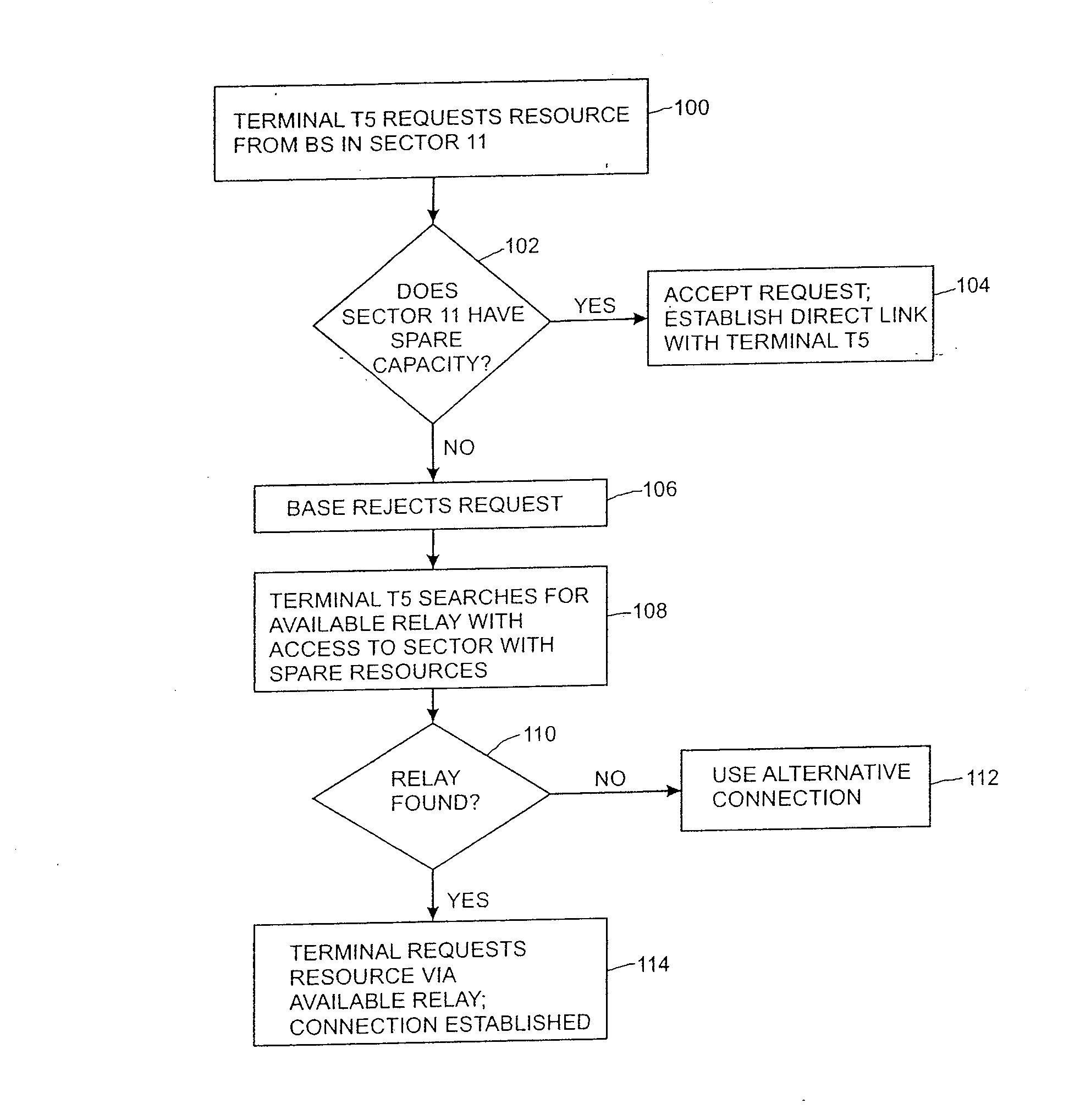
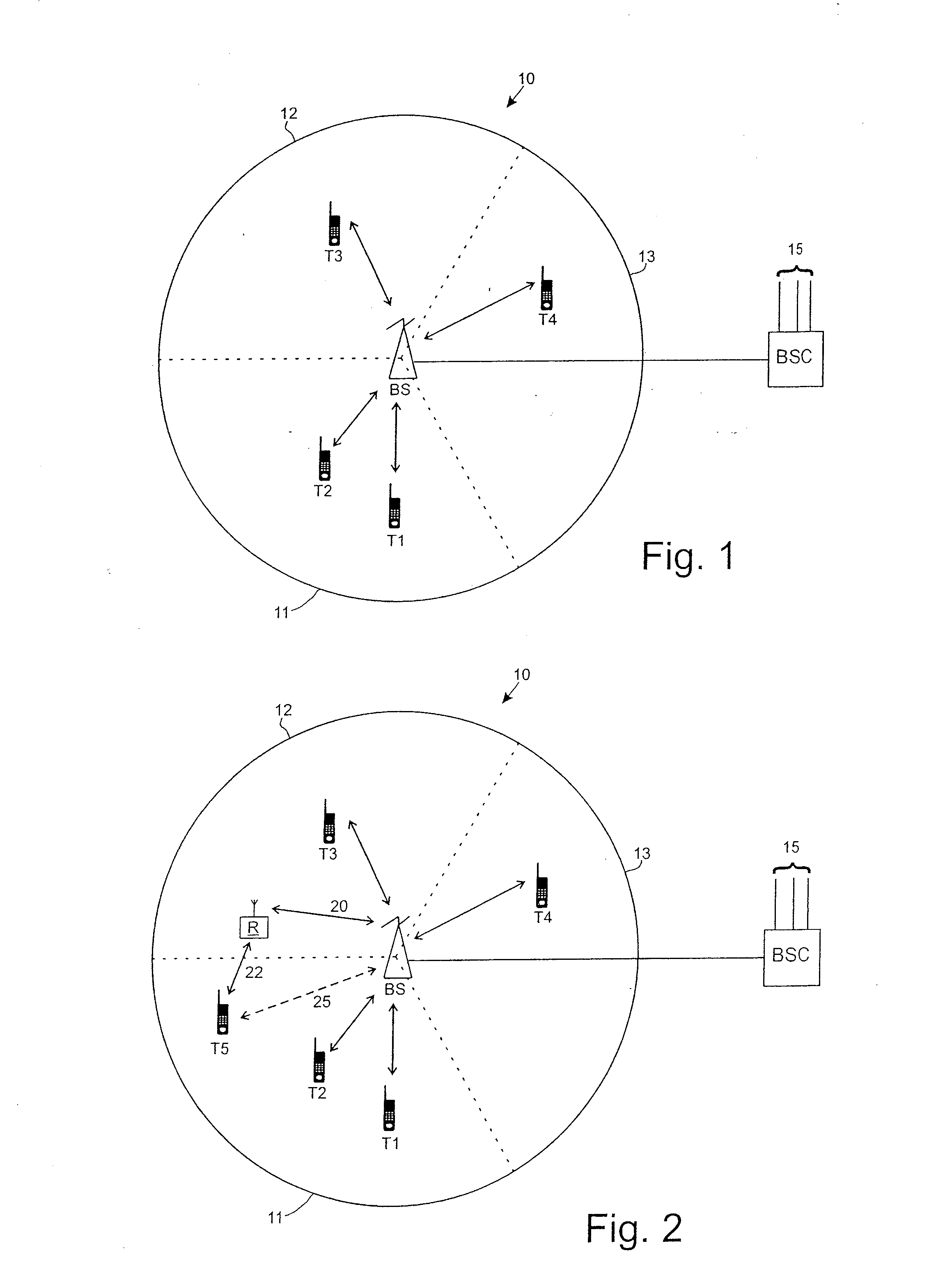
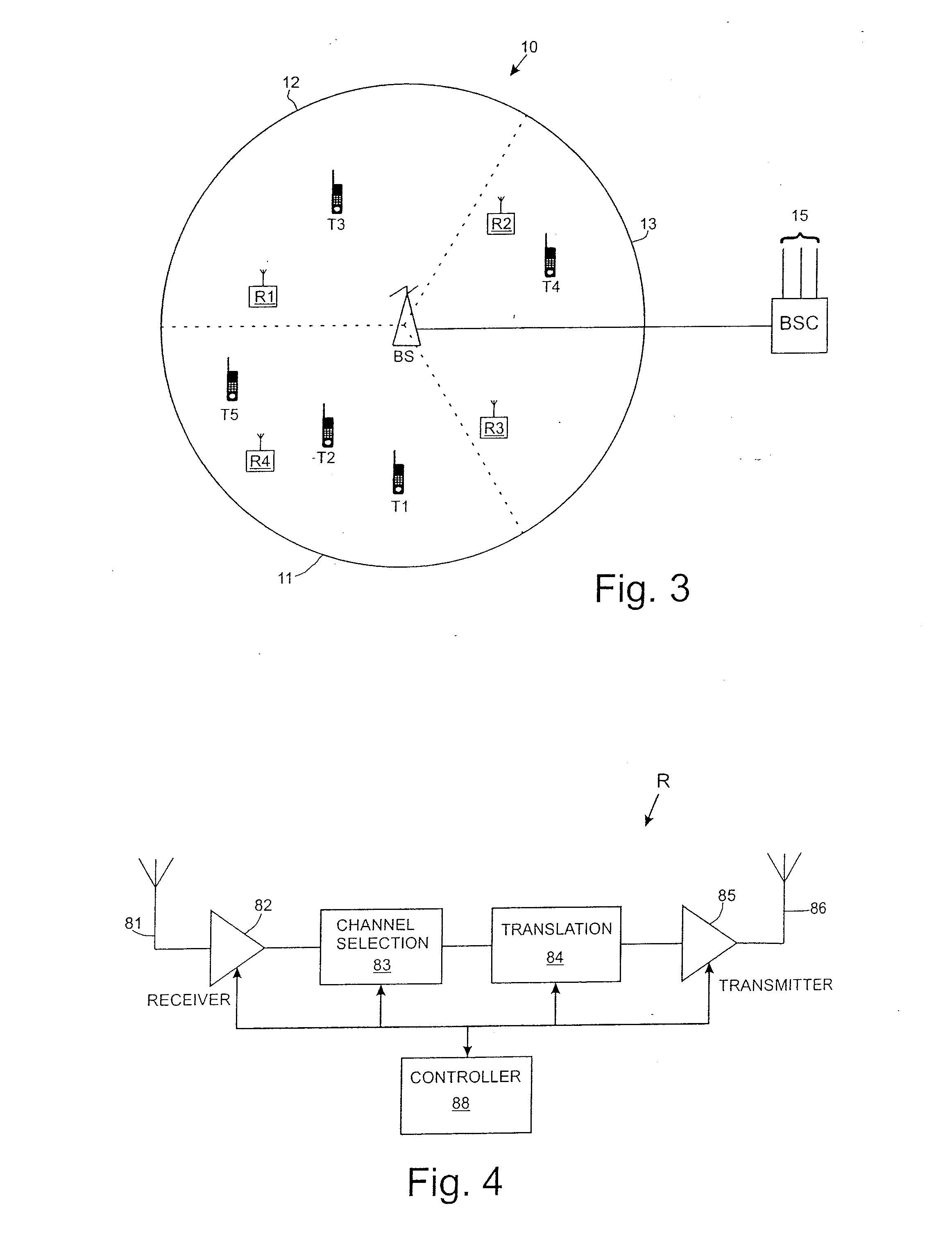
[0037]FIG. 1 shows part of a cellular communications system. One cell 10 of the system is shown, served by a base station BS. The cell 10 is divided into three sectors 11, 12, 13. In a known manner, each sector is served by a separate antenna, or array of antennas, and other transmission equipment at the base station BS. For simplicity, it will be assumed that each sector is defined by a single beam generated by base station BS. Each sector (beam) 11, 12, 13 is allocated spectrum from the total available spectrum resources of the cell 10. The spectrum allocated to an individual sector may be a distinct sub-set of the total available to the cell or spectrum may be reused in other sectors of the cell. In the case of a third generation (3G) system such as UMTS-HSDPA, the resources comprise bearer channels at particular frequencies, each bearer channel being sub-divided into time slots. As terminals T1, T2 within a sector require service they are allocated resources to support uplink (t...


PUM


Abstract

A base station in a wireless communications system defines a plurality of beams which each have an amount of resources for supporting communication links with terminals. A control entity determines if a direct communication link can be supported between a new terminal and a base station using a first beam. If a direct communication link cannot be supported, a relaying equipment is used to provide a multi-hop path between the base station and the terminal. The multi-hop path comprises a link between the base station and the relaying equipment using resources of a different beam. This helps to redistribute load within the cell. The direct communication link can be refused if there are insufficient resources in the first beam, or if accepting the new terminal would cause quality of communication links with existing terminals to deteriorate.

Description

FIELD OF THE INVENTION[0001]This invention relates to wireless communications systems.BACKGROUND TO THE INVENTION[0002]In cellular wireless communications systems a limited range of resources are reused in different, spaced apart, cells. The resources vary according to the type of system, but are generally frequency channels, time slots on a bearer channel, spreading codes or combinations of these. Cells may be subdivided into sectors, with each sector being served by one or more beams formed by directional, higher gain, antennas. The directional antennas increase performance in the uplink and downlink directions by reducing interference, for example, and also help to increase capacity of the overall system as the resources allocated to one beam or sector can be reused in other beams or sectors. Each beam may use a sub-set of the overall resources of the cell or resources may be reused in different beams within the same cell.[0003]One of the problems which can arise in cellular syst...

Claims


Application Information

Patent Timeline
Patent Type & Authority Applications(United States)
IPC IPC(8): H04W28/16H04W88/08H04W88/04
CPCH04B7/2606H04W16/26H04W40/12H04W28/08H04W16/28H04W48/20
Inventor NADEN, JAMESWILSON, FIONA
Owner ROCKSTAR BIDCO
Learn More