
Imaging apparatus and imaging method

a technology of imaging apparatus and imaging method, which is applied in the direction of distance measurement, camera focusing arrangement, printers, etc., can solve the problems of difficult stably and highly precise estimation of distance information, and achieve the effect of low calculation cost, no damage to light amount, and simple camera configuration

Inactive Publication Date: 2012-08-09
PANASONIC CORP
View PDF13 Cites 23 Cited by
  • Summary
  • Abstract
  • Description
  • Claims
  • Application Information

AI Technical Summary

Benefits of technology

[0021]An imaging apparatus according to the present invention makes it possible to generate a depth map of an object based on a plurality of captured images with a simple camera configuration, no damage on the light amount, and a low calculation cost.

Problems solved by technology

However, because this method requires in advance edge information about an image of an object and blur caused by a lens occurs in observed images of a conventional imaging apparatus, thus making it difficult to stably and highly precisely estimate distance information.

Method used


Image

  • Imaging apparatus and imaging method
  • Imaging apparatus and imaging method
  • Imaging apparatus and imaging method

Examples


embodiment 1

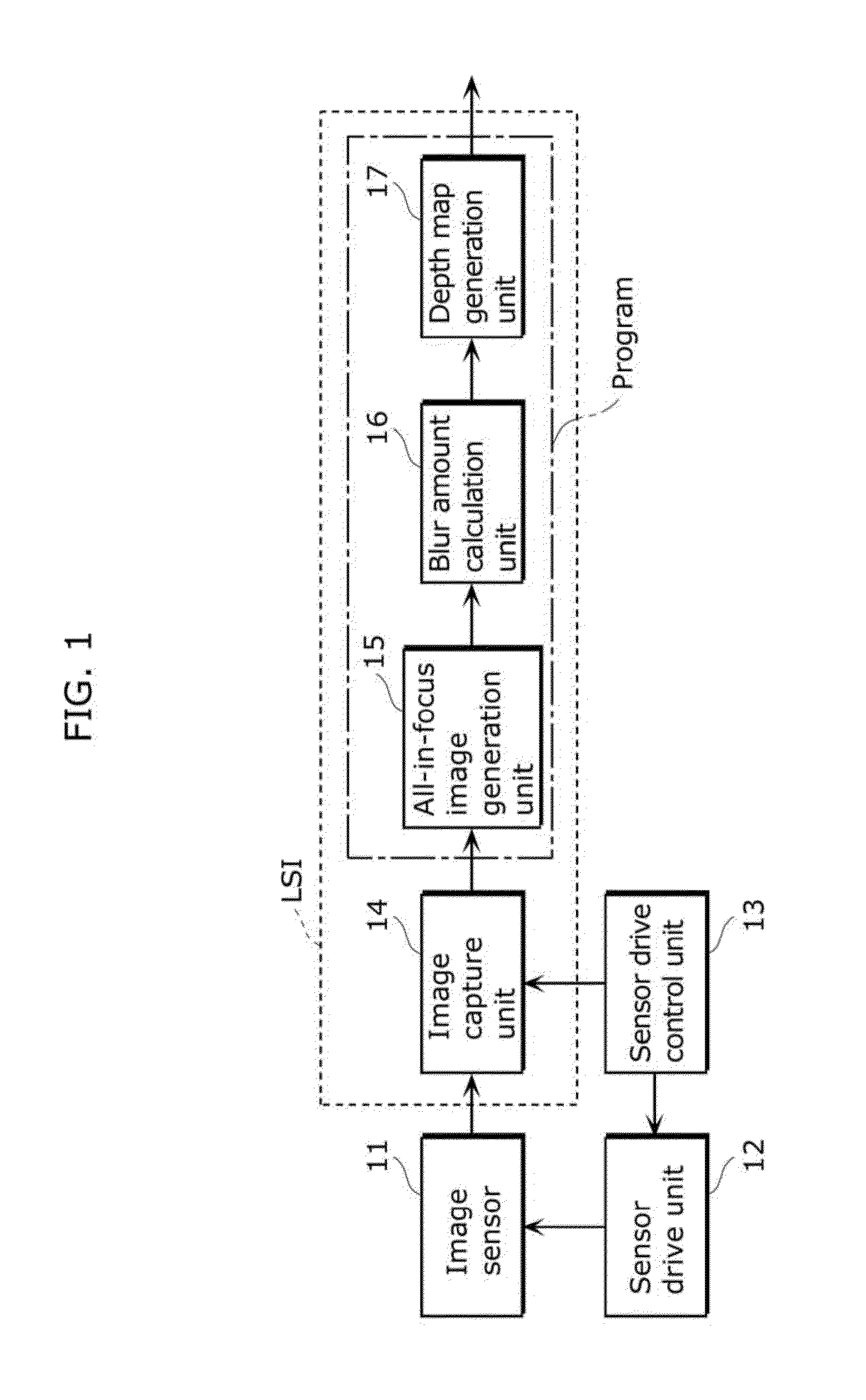
[0037]FIG. 1 is a block diagram of an imaging apparatus according to Embodiment 1 of the present invention.

[0038]In FIG. 1, the imaging apparatus includes an image sensor 11, a sensor drive unit 12, a sensor drive control unit 13, an image capture unit 14, an all-in-focus image generation unit 15, a blur amount calculation unit 16, and a depth map generation unit 17. In a configuration of the imaging apparatus, constituent elements which can be integrated into a single chip of integrated circuit are represented in a dashed-line box, but the image capture unit 14 may be a separate entity from the integrated circuit because the image capture unit 14 is a memory. Meanwhile, in the configuration of the imaging apparatus, constituent elements which can be implemented by a program are represented in a dashed-line box.

[0039]The image sensor 11 is a complementary-symmetry metal-oxide semiconductor (CMOS), a charge-coupled device (CCD), and the like, and captures light at an image capturing ...


PUM


Abstract

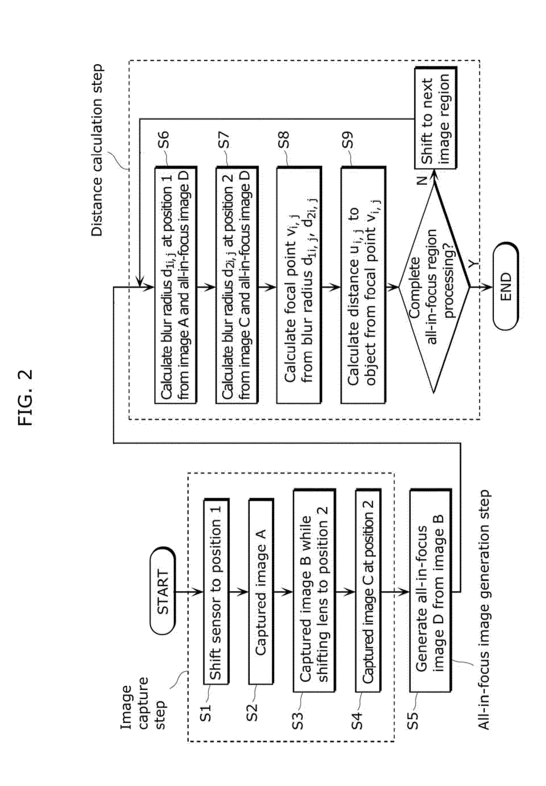
The present invention provides an imaging apparatus which generates, based on a captured image, a depth map of an object with a high degree of precision.A sensor drive unit (12) that shifts an image sensor (11) in an optical axis direction, along with a sensor drive control unit (13), capture images A and C which are focused on a near end side and a far end side of the object, respectively, and an image B by sweeping the image sensor (11) from the near end side to the far end side, an all-in-focus image generation unit (15) generates an all-in-focus image D from the sweep image B, a blur amount calculation unit (16) calculates an amount of blur in each of the partial regions of the images A and B through deconvolution processing in an image of a region corresponding to the all-in-focus image D, and a depth map generation unit (17) generates a distance between the imaging apparatus and the object in each of the image regions, in other words, a depth map, from an amount of blur in regions corresponding to the near end image A and the far end image C and from an optical coefficient value of the imaging apparatus including a focal length of a lens.

Description

TECHNICAL FIELD[0001]The present invention relates to an imaging apparatus or method for measuring, based on a captured image, a distance between an object and the imaging apparatus.BACKGROUND ART[0002]As a conventional method of measuring, based on a captured image, a distance between an object and an imaging apparatus, a method called Depth From Defocus (DFD) is generally known in which a distance is estimated by using blur of an observed image (for example, refer to Non Patent Literature 1). The DFD method which is proposed in Non Patent Literature 1 (hereafter called a Pentland et al. method) pays attention to an edge of an image, estimates an amount of blur from one or two observed images including blur, and estimates a distance to an object based on the amount of blur. However, because this method requires in advance edge information about an image of an object and blur caused by a lens occurs in observed images of a conventional imaging apparatus, thus making it difficult to ...

Claims


Application Information

Patent Timeline
Patent Type & Authority Applications(United States)
IPC IPC(8): H04N13/02
CPCG02B7/365G03B3/10G06T7/0069H04N5/23212G01C3/32G03B13/36H04N5/2226G06T7/571H04N23/959
Inventor TAGAWA, JUNICHISUGITANI, YOSHIAKIKAWAMURA, TAKASHIKIMURA, MASAYUKI
Owner PANASONIC CORP
Learn More