
Tracing of a data processing apparatus

a data processing apparatus and tracing technology, applied in the field of data processing, can solve problems such as the processing of conditional instructions that may be out of order in some data processing devices, and achieve the effects of reducing the trace bandwidth, and reducing the volume of trace data outpu

Active Publication Date: 2012-07-19
ARM LTD
View PDF5 Cites 22 Cited by
  • Summary
  • Abstract
  • Description
  • Claims
  • Application Information

AI Technical Summary

Benefits of technology

[0013]The present invention recognises that providing tracing circuitry capable of independently outputting conditional instruction trace data items and conditional results trace data items provides considerable flexibility and the tracing of conditional instructions that can ameliorate problems associated with known techniques of buffering trace data until a condition associated with a conditionally executed instruction is fully resolved.
[0070]In some embodiments of the diagnostic apparatus according to the present technique, if the diagnostic circuitry encounters a conditional instruction in the program image but a conditional instruction trace item is not currently present in the conditional instruction buffer then the diagnostic circuitry is configured to delay further processing of the corresponding execution thread of the program image until the conditional trace item appears in the conditional instruction buffer. This ensures efficient correlation between the sequence of instructions in the program image and the information received by the diagnostic circuitry. This provides the diagnostic circuitry with the flexibility to cope with receipt and analysis of a compressed trace data stream which some of the trace information must be reconstructed with reference to the program image.

Problems solved by technology

Furthermore, conditional instructions may be processed out of order in some data processors.

Method used


Image

  • Tracing of a data processing apparatus
  • Tracing of a data processing apparatus
  • Tracing of a data processing apparatus

Examples


Embodiment Construction

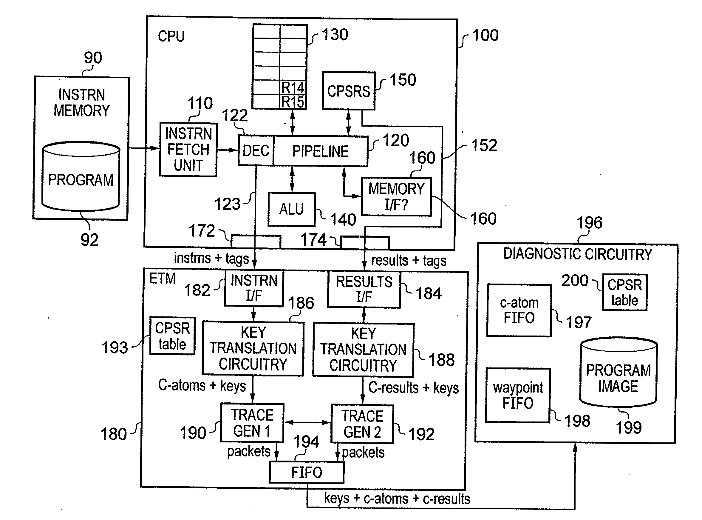
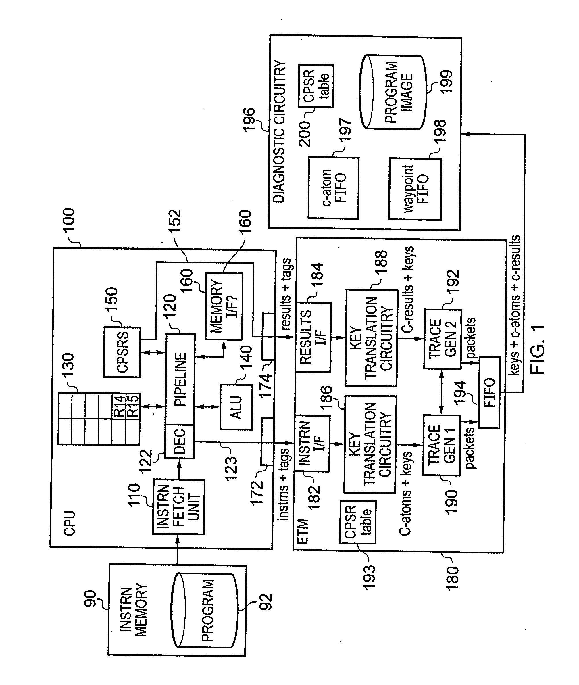
[0107]FIG. 1 schematically illustrates a data processing system according to an embodiment of the present invention. The data processing system comprises: an instruction memory 90; a central processing unit (CPU) 100; an embedded trace macro cell (ETM) 180 containing tracing, circuitry; and diagnostic circuitry 196 for analysing output of the embedded trace macro cell 180.

[0108]The central processing unit 100 comprises: an instruction fetch unit 110; a pipeline 120 including a decode stage 122; a set of registers 130; an arithmetic logic unit (ALU) 140; a set of current program status registers (CPSR) 150; a memory interface 160; an instruction output interface 172; and a results output interface 174.

[0109]The instruction fetch unit 110 fetches instructions from a computer program 92 stored in the instruction memory 90 and supplies those fetched instructions to the decode stage 122 of the pipeline 20. The CPU central processing unit 100 illustrated in FIG. 1 is an ARM pipelined data...


PUM


Abstract

A trace unit, diagnostic apparatus and data processing apparatus are provided for tracing of conditional instructions. The data processing apparatus generates instruction observed indicators indicating execution of conditional instructions and result output indicators indicating output by the data processing apparatus of results of executing respective conditional instructions. The instruction observed indicators and result output indicators are received by a trace unit that is configured to output conditional instruction trace data items and independently output conditional result trace data items enabling separate trace analysis of conditional instructions and corresponding conditional results by a diagnostic apparatus. The instruction observed indicator is received at the trace unit in a first processing cycle of the data processing apparatus whilst result output indicator is received at in a second different processing cycle.

Description

BACKGROUND OF THE INVENTION[0001]1. Field of the Invention[0002]The present invention relates to data processing. More particularly, the present invention relates to tracing of processing activities performed by a data processing apparatus.[0003]2. Description of the Prior Art[0004]It is known to perform tracing of activities of a data processing apparatus in order to verify processor design and to confirm reliable operation of the data processing apparatus when executing program instructions.[0005]It is known to provide a trace unit in association with the data processing apparatus, the trace unit being configured to monitor the processing activities of the data processing apparatus and to generate a sequence of trace data items indicative of those processing activities. An example of such a trace unit is the ARM Embedded Trace Macrocell (ETM) that can be provided either as part of a single System-On-Chip or independently from the processor. The ETM generates trace data for output ...

Claims


Application Information

Patent Timeline
IPC IPC(8): G06F11/22
CPCG06F9/30072G06F9/30094G06F9/30101G06F11/3495G06F11/348G06F9/30145G06F9/30123G06F9/3842G06F11/3461G06F11/3466G06F9/38G06F11/34G06F11/36
Inventor GILKERSON, PAUL ANTHONYHORLEY, JOHN MICHAELGIBBS, MICHAEL JOHN
Owner ARM LTD
Learn More