Eureka AIR delivers breakthrough ideas for toughest innovation challenges, trusted by R&D personnel around the world.

Frost protected injection device

Active Publication Date: 2012-07-19
NOVO NORDISK AS
View PDF10 Cites 108 Cited by
  • Summary
  • Abstract
  • Description
  • Claims
  • Application Information

AI Technical Summary

Benefits of technology

[0007]It is a further object of the invention to provide an injection device allowing for a temporary expansion of the drug containing reservoir which does not damage the injection mechanism and which does not affect the dose accuracy of the device.
[0011]If the drug expands in the reservoir, e.g. due to a temperature decrease leading to a phase change, the forces act on the actuation member via the movable wall, and the configuration of the injection device therefore allows a displacement of the movable wall in the second direction without causing damage to the injection means.
[0014]In an exemplary embodiment, the bias means forms part of the injection means, whereby an injection device is provided which is capable of both automatically injecting a dose of the liquid drug and automatically returning the actuation member to its original position upon a discontinuation of a force acting in the second direction, without requiring extra construction parts.
[0020]The removable cap may be adapted to cover an outlet portion of the injection device, such as a needle holding portion or a jet injection nozzle, when the injection device is not in use. Thereby the removable cap is capable of e.g. protecting a needle mounted on the needle holding portion, preventing needle sticks and preventing accidental spilling of the liquid drug. The cap can be removed when it is desired to inject a dose, thereby uncovering the needle holding portion.
[0031]The injection device may further comprise a housing, and the engagement structure may provide a coupling between the housing and the actuation member for preventing movements of the actuation member in the second direction relative to the housing, the coupling being configured to reversibly decouple the housing and the actuation member in response to a force acting on the actuation member in the second direction of a magnitude which is equal to or greater than the threshold value.
[0061]Arrangements as the above described have the effect that should the drug deliberately or inadvertently be exposed to temperatures that causes it to freeze it is free to expand in the reservoir because the construction of the injection device, e.g. the configuration of the injection mechanism, allows the movable wall to move in another direction than the one intended for injection of the drug without resulting in damages to the device. Further, since the volume of drug delivered in the course of an injection depends only on a firm engagement between the actuation member and the drive member and on the distance between the first retention plateau and the second retention plateau, the arrangements guarantee that the dose injected following a drug freeze and thawing out is the same as it would be otherwise. This is because following the thawing out of the drug the actuation member and the drive member will be positioned relative to the guide member such that when a user operates the injection device the components will undergo the same movements as they would under normal circumstances. Specifically, the drive member and the actuation member will be in firm engagement when the drive member is positioned on the first retention plateau. In other words a freezing of the drug will not affect the dose accuracy of the injection device.

Problems solved by technology

Other injection devices are prefilled when delivered to the user and can only be used until the drug reservoir has been emptied.
During transportation and handling of the injection device there is, however, a risk of introducing an undesired slack between the piston rod and the piston which should then be eliminated before an injection, e.g. by carrying out a priming operation.
If an injection device accommodating a liquid drug is for any reason exposed to temperatures below the liquid drug's freezing point, the liquid will expand in the reservoir causing a relatively large pressure on the reservoir walls, including the piston.
Especially for injection devices employing a unidirectional ratchet and pawl drive mechanism the coupling between the piston rod and the piston rod drive may not be able to withstand such a large force, potentially leading to breakage of vital components in the device, thereby either introducing a risk of malfunction or rendering the device useless.
However, accidentally placing the drug container too close to a highly active cooling element may cause the drug to freeze.

Method used


Image

  • Frost protected injection device
  • Frost protected injection device
  • Frost protected injection device

Examples


Embodiment Construction

[0094]When in the following relative expressions, such as “clockwise” and “counter-clockwise” and “proximally” and “distally”, are used, these refer to the appended figures and not necessarily to an actual situation of use. The shown figures are schematic representations for which reason the configuration of the different structures as well as their relative dimensions are intended to serve illustrative purposes only.

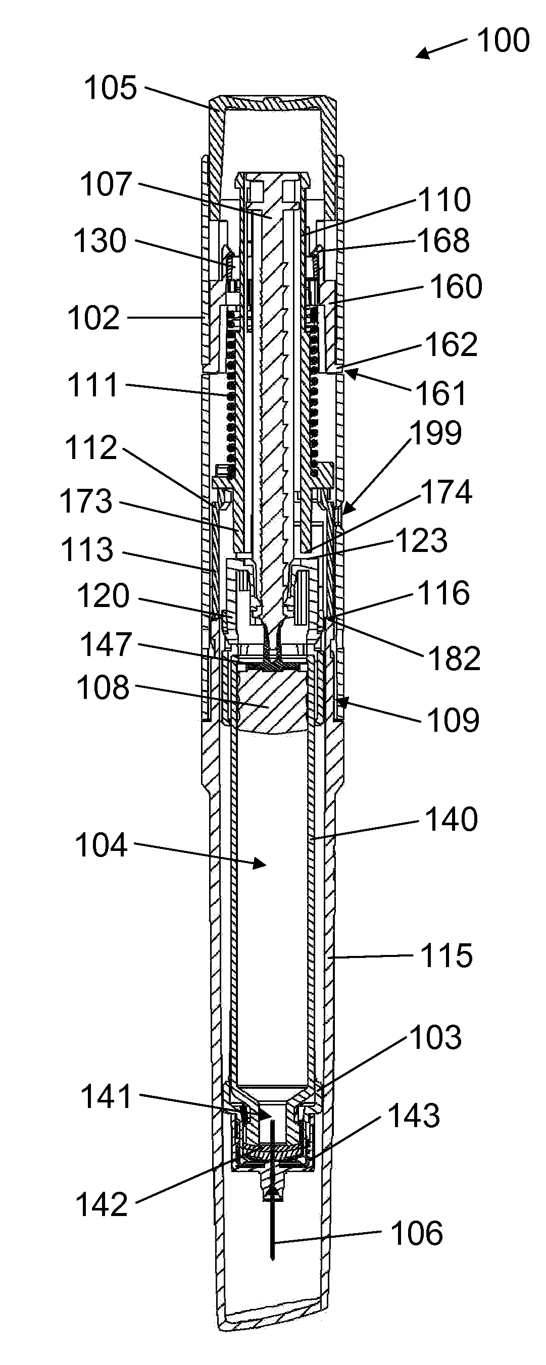
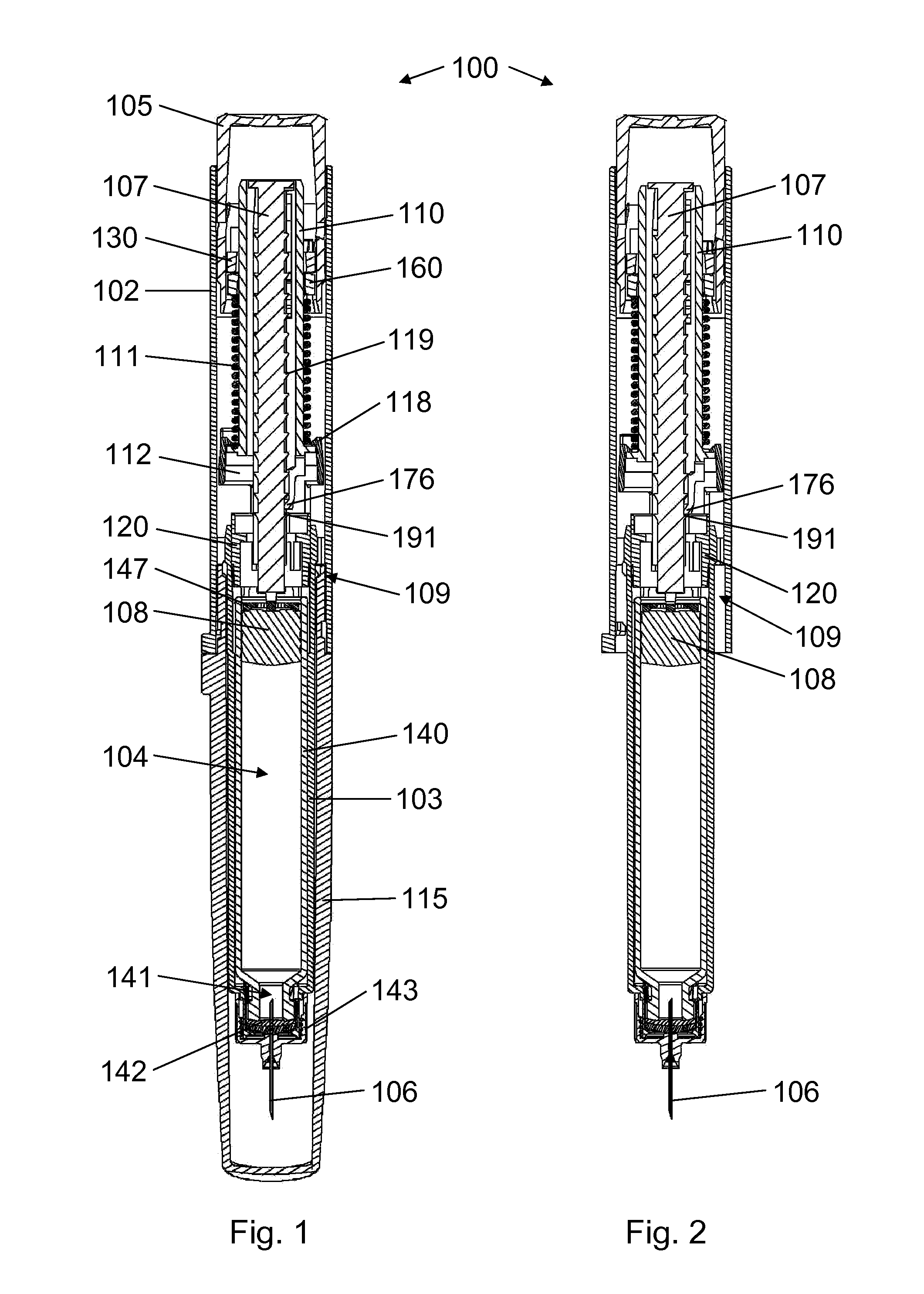
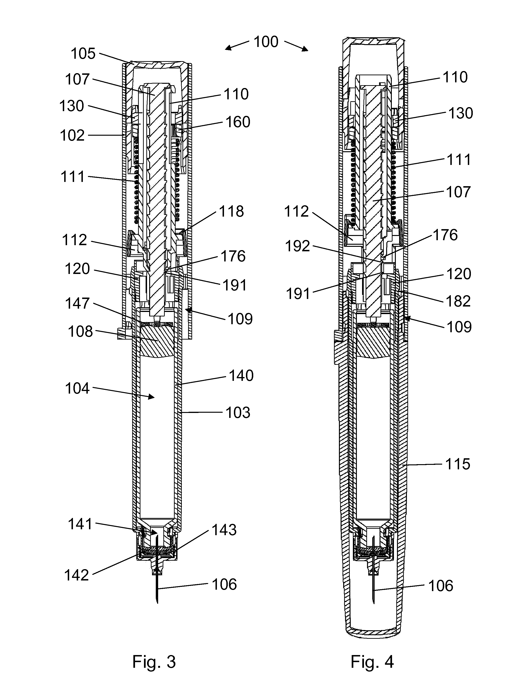
[0095]FIG. 1 shows an injection device 100 according to an exemplary embodiment of the invention. The injection device 100 is in a loaded state as delivered from the manufacturer, i.e. it has not yet been used for injection. The injection device 100 comprises a housing 102 and a cartridge holding part 103 for supporting a cartridge 104 which contains the liquid drug. The liquid drug is positioned between a piston 108, which is capable of moving axially in the cartridge 104, a tubular cartridge wall 140, and a self-sealing septum 142 covering a drug outlet 141. The liqui...


PUM


Abstract

The invention relates to an injection device (100, 200, 300) which is capable of resisting proximal movements of a piston rod (107, 207, 307) relative to a housing (102, 202, 302), when the piston rod (107, 207, 307) is subjected to proximally directed forces below a threshold magnitude, and of allowing reversible proximal movements of the piston rod (107, 207, 307) relative to the housing (102, 202, 302), when the piston rod (107, 207, 307) is subjected to proximally directed forces of or above the threshold magnitude.

Description

FIELD OF THE INVENTION[0001]The present invention relates to an injection device for administering a liquid drug.BACKGROUND OF THE INVENTION[0002]Injection devices, such as injection pens, are widely used for self administration of liquid drugs by people in need of therapeutic treatment. Many injection devices are capable of repeatedly setting and injecting either a fixed or a variable volume of drug upon operation of respective dose setting and injection mechanisms in the device. Some injection devices are adapted to be loaded with a prefilled drug reservoir containing a volume of drug which is sufficient to provide for a number of injectable doses. When the reservoir is empty, the user replaces it with a new one and the injection device can thus be used again and again. Other injection devices are prefilled when delivered to the user and can only be used until the drug reservoir has been emptied. The various injection devices typically expel the drug by advancing a piston in the r...

Claims


Application Information

Patent Timeline
IPC IPC(8): A61M5/31
CPCA61M5/24A61M2205/6081A61M5/3146A61M5/315A61M5/31505A61M5/31551A61M5/3156A61M5/3157A61M5/31585A61M5/31593A61M2005/2407A61M2005/31508A61M2005/3152A61M2205/581A61M2205/583A61M5/2425
Inventor BOM, LARS MORTENENGGAARD, CHRISTIAN PETEROSTERGAARD, BRIANJENSEN, JACOB KOLLERUP
Owner NOVO NORDISK AS
Why Eureka
Eureka Blog
Learn More