
Bypass Monitor for Fuel Supply System

a monitor and fuel supply technology, applied in the direction of machines/engines, fluid tightness measurement, instruments, etc., can solve the problems of failure to start the turbine engine, reduce the volumetric efficiency and capacity of the fuel pump, and the pressure differential across the metering valve rises

Inactive Publication Date: 2012-07-05
HAMILTON SUNDSTRAND CORP
View PDF8 Cites 25 Cited by
  • Summary
  • Abstract
  • Description
  • Claims
  • Application Information

AI Technical Summary

Problems solved by technology

The increase in fuel pump speed increases the flow of fuel which will cause a rise in the pressure differential across the metering valve.
These fuel system pressures may cause internal leakage of fuel system components, which may reduce the volumetric efficiency and capacity of the fuel pump over time.
This loss of fuel pump capacity over time may lead to a failure to start the turbine engine, or a failure to reach maximum thrust on take off.

Method used


Image

  • Bypass Monitor for Fuel Supply System
  • Bypass Monitor for Fuel Supply System
  • Bypass Monitor for Fuel Supply System

Examples


Embodiment Construction

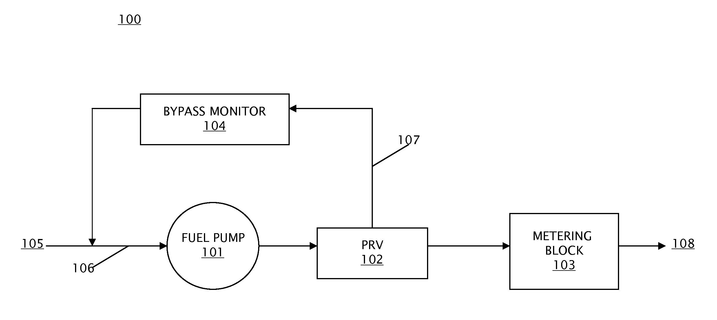
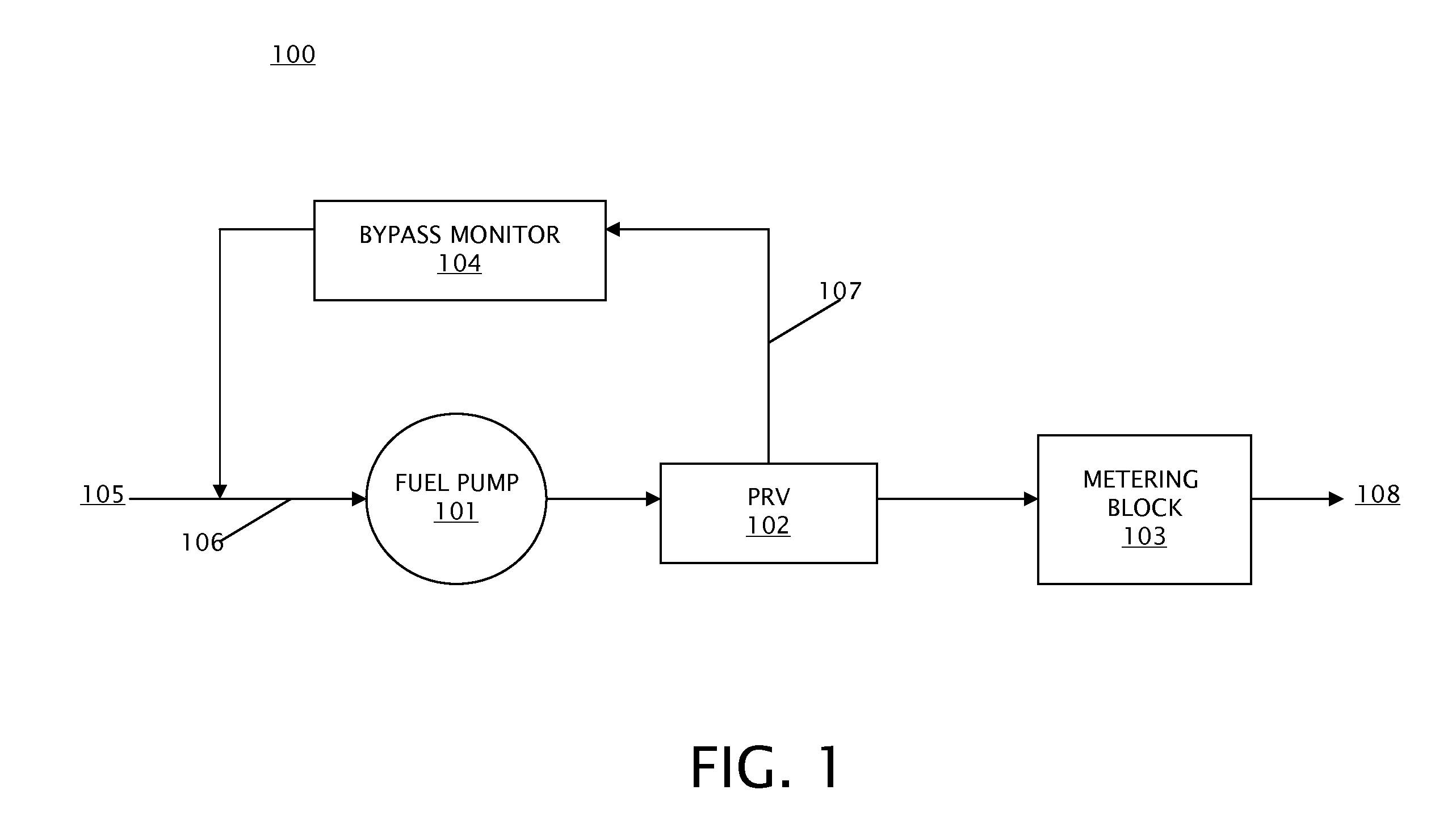
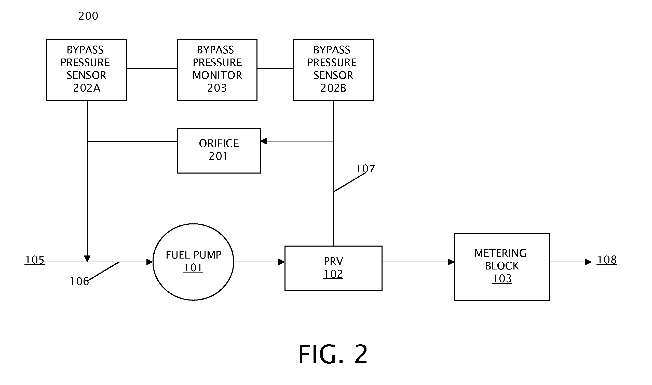
[0016]Embodiments of a bypass flow monitor for a fuel supply system and methods of monitoring fuel supply system health using a bypass flow monitor are provided, with exemplary embodiments being discussed below in detail. Fuel pumps for jet turbine engines are designed to have extra capacity that is above what the turbine engine requires for operation at any given operating point. The excess flow is referred to as bypass flow. There is a third flow component called leakage flow. As the pump wears over time, the bypass flow decreases as leakage flow increases, and pump efficiency degrades. Therefore, a change in the amount of bypass flow in the fuel supply system may be used to detect increased leakage in the fuel supply system. The increased leakage indicates a loss of performance margin in the fuel supply system.

[0017]The monitoring of bypass flow may occur at different points in the pump operating range to diagnose the type of degradation that is occurring. Early detection of exce...


PUM


Abstract

A method for monitoring a fuel supply system for a turbine engine, the fuel supply system comprising a fuel pump and a pressure regulation valve configured to receive fuel from an outlet of the fuel pump includes determining by a bypass monitor an amount of bypass flow in a bypass path located between the pressure regulation valve and an inlet of the fuel pump; determining an amount of leakage flow in the fuel supply system by the bypass monitor based on the bypass flow; and determining whether the leakage flow exceeds a predetermined threshold by the bypass monitor, and in the event the leakage flow exceeds the predetermined threshold, indicating a need for maintenance of the fuel supply system.

Description

FIELD OF INVENTION[0001]The subject matter disclosed herein relates generally to the field of fuel supply systems, and more specifically to a bypass monitor for monitoring the health of a fuel pump in a fuel supply system.DESCRIPTION OF RELATED ART[0002]Fuel supply systems for aircraft gas turbine engines may include a fixed positive displacement pump, such as a vane or gear pump, to pressurize fuel for subsequent delivery to the engine. The fuel pump provides a low flow during engine low speed engine starting conditions with a fuel volume that is a function of the speed at which the pump is rotating. The relation of the change in volumetric output for a change in fuel pump speed is linear in nature.[0003]The demand for fuel increases as the engine speed increases, although when measured as a function of the percentage of fuel pump output, demand for fuel is greatest at either low speeds (engine start) or high speeds (takeoff). Therefore, in order to provide the desired flow of fuel...

Claims


Application Information

Patent Timeline
Patent Type & Authority Applications(United States)
IPC IPC(8): F02C6/00G01M3/28
CPCF02C9/36F02C7/232F02C7/236F02C9/263F02C9/28
Inventor POISSON, RICHARD A.HEITZ, STEVEN A.
Owner HAMILTON SUNDSTRAND CORP
Learn More