Imaging lens
- Summary
- Abstract
- Description
- Claims
- Application Information
AI Technical Summary
Benefits of technology
Problems solved by technology
Method used
Image

Examples
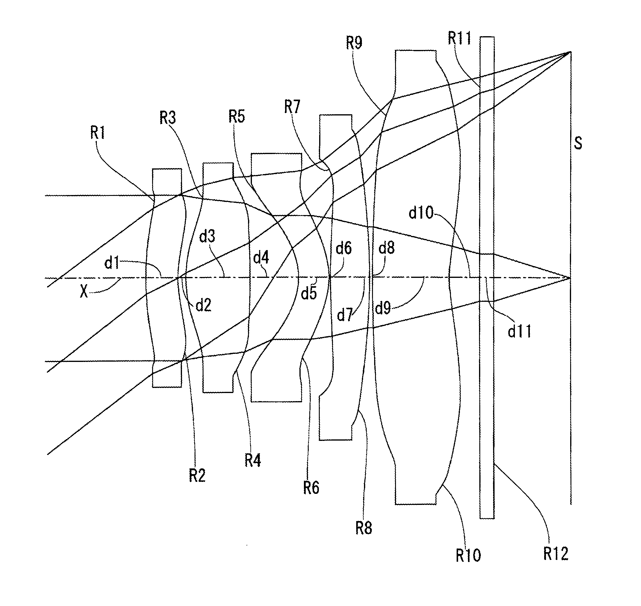
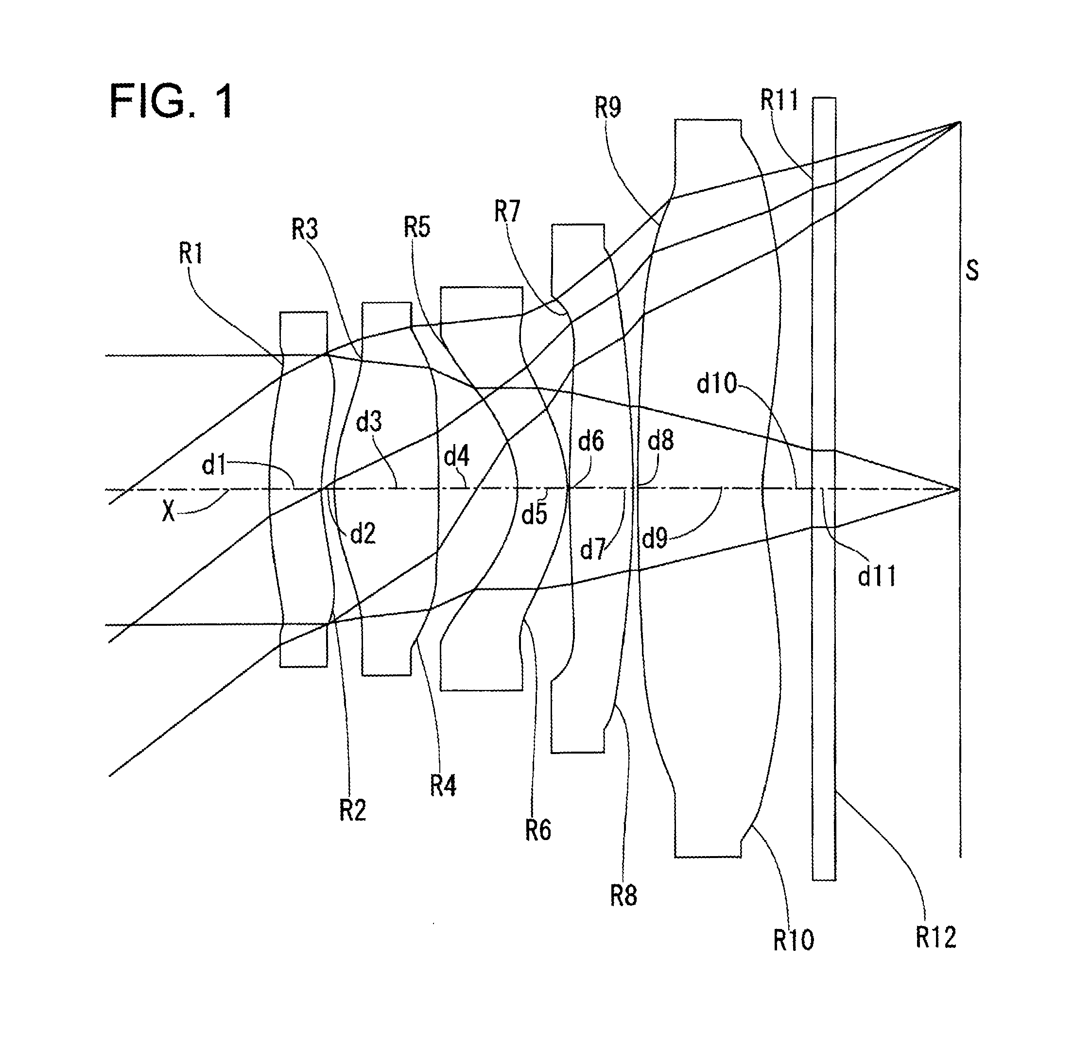
embodiment 1
[0046]Aspheric surface data
First surface
Aspheric coefficient
K=−8.2055
A4=−0.14250673E+1
A6=−0.15398119E+2
A8=0.29721504E+3
A10=−0.82925962E+4
A12=0.58698022E+5
A14=−0.75034191E+5
A16=−0.43083295E+6
[0047]Second surface
Aspheric coefficient
K=0.9087
A4=−0.21905004E+2
A6=0.21209148E+3
A8=−0.45499369E+4
A10=0.61978045E+5
A12=−0.43700376E+6
A14=0.12528813E+7
[0048]Third surface
Aspheric coefficient
K=0.0249
A4=−0.11867183E+2
A6=0.10211791E+3
A8=−0.98096964E+3
A10=−0.25571016E+5
A12=−0.25571016E+5
A14=−0.70814894E+7
A16=0.24370137E+8
[0049]Fourth surface (the diffraction optics surface)
Aspheric coefficient
K=−0.43743450E+3
A4=−0.88736166E+0
A6=−0.45096375E+2
A8=0.93537909E+3
A10=−0.56944080E+5
A12=0.11195156E+7
A14=−0.91414818E+7
A16=0.27984495E+8
[0050]Optical path difference function coefficient
B2=−0.54094213E+2
B4=0.23812736E+2
B6=0.11920174E+5
B8=−0.87589610E+5
[0051]Reference wavelength of the optical path difference function λ0=520.0 nm
Fifth surface
Aspheric coefficient
K=−0.8864
A4=0.59191096E+1
A6=−0.15537832E+3
A8=0.168897...
embodiment 2
[0060]The imaging lens related to Embodiment 2 has approximately the same lens configuration as Embodiment 1. However, in the present embodiment, the rim of the effective diameter of the surface R1 on the object side of the first lens doubles the effect of the diaphragm.
[0061]Table 3 shows the curvature radius R of each lens, the surface interval d of each surface on the optical axis, the refractive index n at e-ray of the lens material, and the Abbe number v, in the case where the focal length of all system of embodiment 2 is normalized to f=1.0. Further, the F-number and a half angle of image ω of embodiment 2 are indicated at the bottom line of the table. In Table 3 and following tables, the numbers corresponding to each reference sequentially increase from the object side.
TABLE 3Embodiment 2Surface dataEffectiveSurface No.RdnvdiameterObject surface∞∞ 1 (diaphragm)1.02200.22271.5369056.30.278 20.75600.01800.335 30.52210.20551.5369056.30.338 4 (diffraction−2.51280.14280.384optics ...
embodiment 3
[0079]Aspheric surface data
First surface
Aspheric coefficient
K=−8.2055
A4=−0.50032628E+01
A6=0.13580390E+02
A8=−0.33977541E+03
A10=−0.75255085E+03
A12=−0.81068236E+05
A14=0.27750527E+07
A16=−0.24705214E+08
A18=0.62088156E+08
[0080]Second surface
Aspheric coefficient
K=1.0000
A4=−0.28042280E+02
A6=0.18906879E+03
A8=−0.49233304E+04
A10=0.91055287E+05
A12=−0.56975207E+06
A14=−0.20226564E+07
A16=0.24506630E+08
[0081]Third surface
Aspheric coefficient
K=−0.1465
A4=−0.14287467E+02
A6=0.13389684E+03
A8=−0.43787035E+04
A10=0.81012994E+05
A12=−0.35563865E+06
A14=−0.40847121E+07
A16=0.28295150E+08
[0082]Fourth surface (the diffraction optics surface)
Aspheric coefficient
K=−0.43743450E+03
A4=−0.30094662E+01
A6=0.56498257E+02
A8=−0.23232519E+03
A10=−0.40772331E+05
A12=0.87285611E+06
A14=−0.76897077E+07
A16=0.24751730E+08
[0083]The optical path difference function coefficient
B2=−0.64773767E+02
B4=0.96326411E+03
B6=−0.21530671E+05
B8=0.25286771E+06
B10=−0.10532158E+07
[0084]Reference wavelength of the optical path difference function λ0=52...
PUM
 Abstract
Description
Claims
Application Information
 - R&D
- Intellectual Property
- Life Sciences
- Materials
- Tech Scout
- Unparalleled Data Quality
- Higher Quality Content
- 60% Fewer Hallucinations
Browse by: Latest US Patents, China's latest patents, Technical Efficacy Thesaurus, Application Domain, Technology Topic, Popular Technical Reports.
© 2025 PatSnap. All rights reserved.Legal|Privacy policy|Modern Slavery Act Transparency Statement|Sitemap|About US| Contact US: help@patsnap.com