Wireless power feeder, wireless power receiver, and wireless power transmission system

Active Publication Date: 2012-06-28
TDK CORPARATION
View PDF5 Cites 15 Cited by
  • Summary
  • Abstract
  • Description
  • Claims
  • Application Information

AI Technical Summary

Benefits of technology

[0009]Incidentally, from the perspective of the power transmission efficiency, it is preferred that the degree of coupling (coupling coefficient) between the power receive coil and the power receive load coil of the power receive resonance circuit be high. However, when the degree of coupling between the power receive coil and the power receive load coil is high, a low load impedance lowers a Q value of the power receive resonance circuit, reducing a resonance current of the power receive resonance circuit. This eventually lowers the power transmission efficiency.

Problems solved by technology

This eventually lowers the power transmission efficiency.
Therefore, the decrease in the power transmission efficiency described above becomes prominent as the relative distance between the power feed resonance circuit and the power receive resonance circuit increases.

Method used


Image

  • Wireless power feeder, wireless power receiver, and wireless power transmission system
  • Wireless power feeder, wireless power receiver, and wireless power transmission system
  • Wireless power feeder, wireless power receiver, and wireless power transmission system

Examples


first embodiment

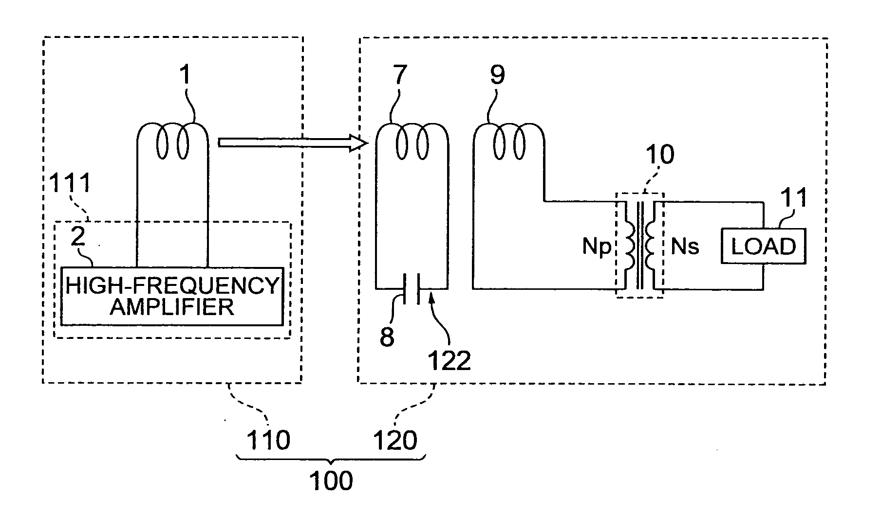
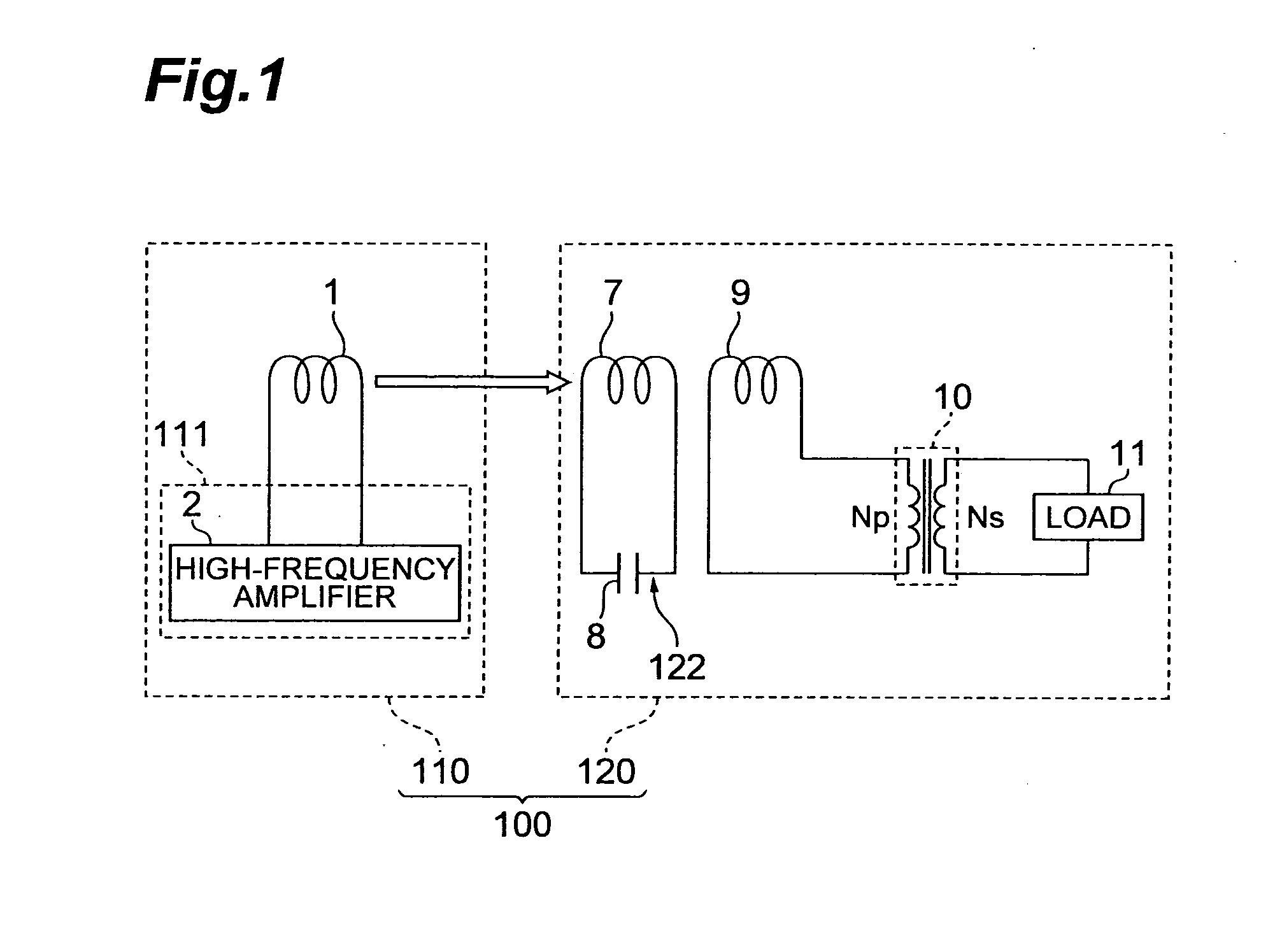
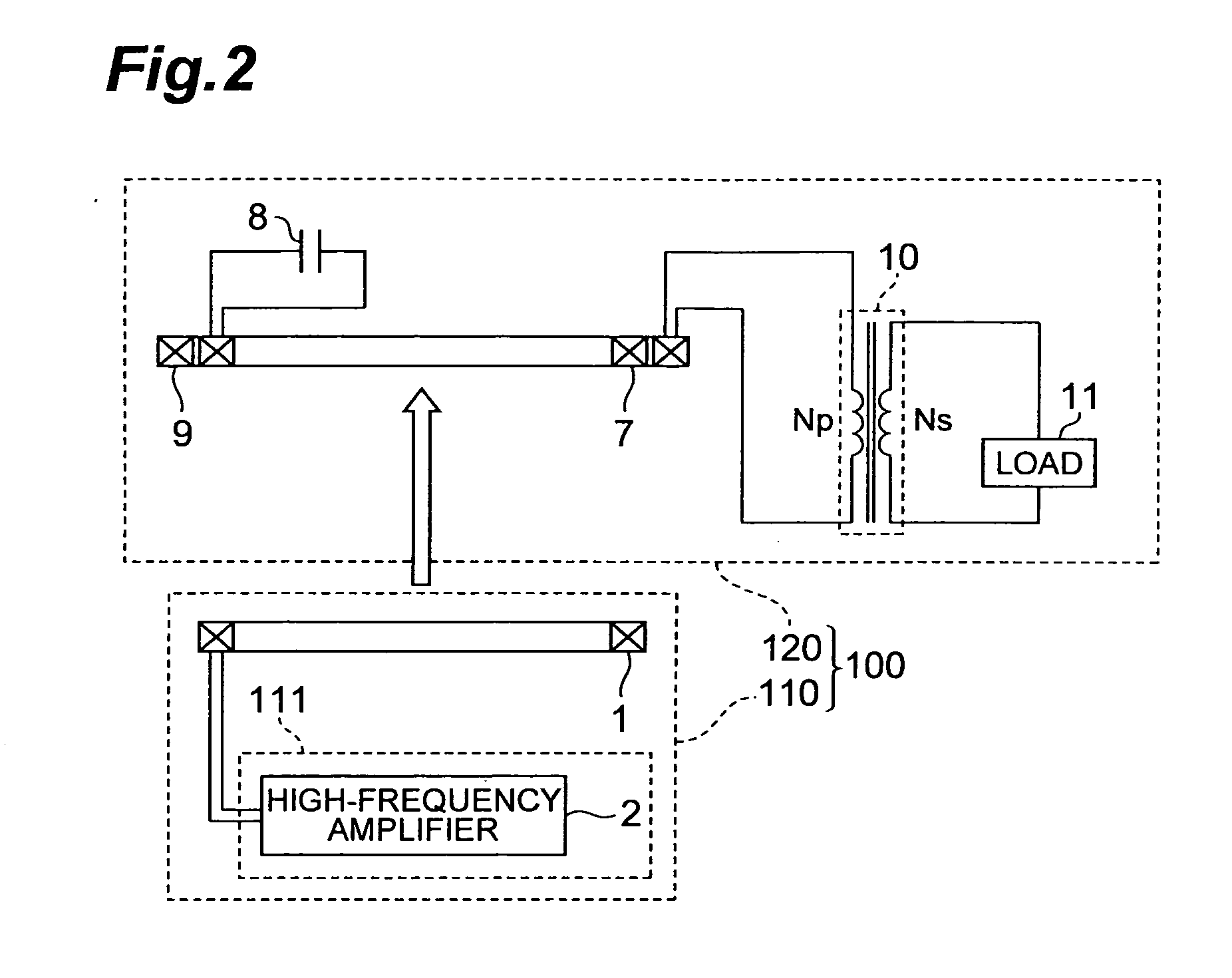
[0043]FIG. 1 is a schematic diagram showing a schematic electrical configuration of a wireless power transmission system according to a first embodiment of the present invention. FIG. 2 is a cross-sectional diagram showing physical structures of a power feed coil, power receive coil and power receive load coil shown in FIG. 1. A wireless power transmission system 100 shown in FIGS. 1 and 2 has a wireless power feeder 110 and wireless power receiver 120 and transmits power from the wireless power feeder 110 to the wireless power receiver 120 by a non-contact method. Note that FIGS. 1 and 2 each schematically show the wireless power feeder.

(First Characteristics)

[0044]First, the wireless power receiver 120 is described. The wireless power receiver 120 has a power receive resonance circuit 122 configured by a power receive coil 7 and power receive capacitor 8, a power receive load coil 9, and output transformer (impedance converter) 10.

[0045]The power receive coil 7 of the power receiv...

example

[0070]Hereinafter, the wireless power transmission system 100 of the present embodiment shown in FIGS. 1, 2 and 8 is produced and evaluated in an example. This evaluation is a comparative evaluation with respect to the prior art shown in FIG. 3.

[0071]Similarities between the example and the prior art

[0072]resonance frequency of the power receive resonance circuit 122: Approximately 170 kHz to 200 kHz

[0073]The power feed coil 1 and the power receive coil 7: An inner diameter of approximately Φ160 mm and a thickness of approximately 10 mm with Litz copper wire in order to reduce the skin effect.

[0074]External diameter of the power receive load coil 9: A diameter of approximately Φ200 mm and a thickness of approximately 10 mm with Litz copper wire in order to reduce the skin effect.

[0075]Characteristics of the Example

[0076]The output transformer 10: A ferrite core was used (e.g., general EE type or EI type ferrite core), with the impedance on the primary side of approximately 500Ω

[0077...

second embodiment

[0082]FIG. 12 is a diagram showing an electrical configuration of a wireless power transmission system according to a second embodiment of the present invention. A wireless power transmission system 100B may have a wireless power receiver 120B in place of the wire less power receiver 120.

[0083]Unlike the wireless power receiver 120 of the first embodiment that has the output transformer 10, the wireless power receiver 120B has an output transformer 10B. The output transformer 10B is different than the transformer 10 in that the output transformer 10B has four windings Ns1 to Ns4 on the secondary side so as to be able to produce four outputs. Loads 11a to 11d can be connected to the secondary windings Ns1 to Ns4, respectively. The primary impedance of the output transformer 10B is, for example, 500Ω, whereas the impedances obtained when the loads 11a to 11d are observed from the secondary side of the output transformer 10B are 10Ω, 50Ω, 100Ω and 300Ω, respectively. The number of turn...


PUM


Abstract

A wireless power receiver according to an embodiment of the present invention is a wireless power receiver which acquire power by a non-contact method from a wireless power feeder, the wireless power receiver having: a power receive resonance circuit that includes a power receive coil and power receive capacitor and acquires power from a power feed coil of the wireless power feeder by means of the power receive coil on the basis of a magnetic field resonance effect between the power feed coil and the power receive coil; a power receive load coil that receives the power fed from the power receive coil by a non-contact method; and an impedance converter that is arranged between the power receive load coil and a load and in which a primary impedance connected to the power receive load coil is higher than a secondary impedance connected to the load.

Description

CROSS REFERENCE TO RELATED APPLICATION[0001]This application claims priority to U.S. Provisional Application No. 61 / 427,611 filed on Dec. 28, 2010 by the same Applicant, which is hereby incorporated by reference in its entirety.BACKGROUND OF THE INVENTION[0002]1. Field of the Invention[0003]The present invention relates to a wireless power feeder, wireless power receiver and wireless power transmission system for transmitting power by a non-contact method.[0004]2. Related Background Art[0005]Japanese Patent Application Publication No. 2010-233442 discloses a wireless power transmission system for transmitting power from a wireless power feeder to a wireless power receiver by a non- contact method (wirelessly). In this wireless power transmission system, a wireless power feeder 1 and wireless power receiver 2 have a power feed resonance circuit 12 and power receive resonance circuit 21, respectively, wherein non-contact power transmission is carried out using a magnetic field resonan...

Claims


Application Information

Patent Timeline
IPC IPC(8): H01F38/14
CPCH02J17/00H02J50/12H02J50/90
Inventor URANO, TAKASHI
Owner TDK CORPARATION
Why Eureka
Try Eureka