Spark plug

a technology of spark plugs and plugs, which is applied in the direction of cathode ray tubes/electron beam tubes, electrical discharge tubes, electrical apparatus, etc., can solve the problems of excessive closeness between the metallic shell and the insulator, and achieve the effect of simple and easy method

Active Publication Date: 2012-06-21
NGK SPARK PLUG CO LTD
View PDF0 Cites 5 Cited by
  • Summary
  • Abstract
  • Description
  • Claims
  • Application Information

AI Technical Summary

Benefits of technology

[0017]According to the above-described configuration 1, the center electrode has a space-forming portion which forms an annular space in cooperation with the wall surface of the axial hole, and a portion of the insulator which faces the front end of the metallic shell and at which penetration is likely to occur has a reduced thickness of 0.6 mm or less. Therefore, occurrence of penetration of discharge through the insulator is very likely. However, according to the above-described configuration 1, a large distance of 0.4 mm or greater (as measured along the axis) is secured between the boundary portion and the front end of the metallic shell, where the boundary portion is formed between the space-forming portion and the main body portion (that is, between portions at which electric field intensity becomes relatively high). That is, although electric fields extending along the radial direction are mainly formed at the boundary portion between the space-forming portion and the main body portion and the boundary portion between the front end surface and inner circumferential surface of the metallic shell, concentration of electric field intensity can be restrained effectively by relatively greatly separating both the boundary portions in the axial direction (that is, in the direction intersecting the direction of the electric fields). As a result, penetration of discharge through the insulator can be prevented more reliably.
[0036]From the viewpoint of restraining concentration of electric field intensity, the boundary portion between the space-forming portion and the main body portion and the front end of the metallic shell may be separated in the radial direction (the direction orthogonal to the axis). However, in the case of a spark plug in which the metallic shell has a nominal diameter of M10 or less as in the above-described configuration 8, separating the two boundary portions in the radial direction is difficult. Therefore, employment of the above-described configuration 1, etc. (separating the two boundary portions along the axial direction) is a very simple and easy method for realizing the restraint of concentration of electric field intensity in such a spark plug. That is, the above-described configuration 1, etc. is particularly meaningful for spark plugs in which the nominal diameter is M10 or less, and separating the two boundary portions in the radial direction is difficult.

Problems solved by technology

However, merely reducing the diameter of only the metallic shell may result in excessive closeness between the metallic shell and the insulator.

Method used


Image

  • Spark plug
  • Spark plug
  • Spark plug

Examples


Embodiment Construction

Mode for Carrying out the Invention

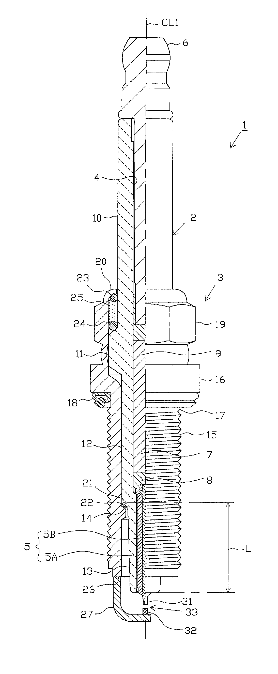
[0046]One embodiment will next be described with reference to the drawings. FIG. 1 is a partially sectioned front view showing a spark plug 1. Notably, in FIG. 1, the direction of an axis CL1 of the spark plug 1 is referred to as the vertical direction. In the following description, the lower side of the spark plug 1 in FIG. 1 is referred to as the front end side of the spark plug 1, and the upper side as the rear end side.

[0047]The spark plug 1 includes a tubular insulator 2, a tubular metallic shell 3, which holds the insulator 2 therein, etc.

[0048]The insulator 2 is formed from alumina or the like by firing, as well known in the art. The insulator 2, as viewed externally, includes a rear trunk portion 10 formed on the rear end side; a large-diameter portion 11, which is located frontward of the rear trunk portion 10 and projects radially outward; an intermediate trunk portion 12, which is located frontward of the large-diameter portion 11 and is...


PUM


Abstract

A spark plug includes a tubular metallic shell; a tubular insulator in the tubular metallic shell located at a front end of the metallic shell and having an axial hole extending in the axial direction; and a center electrode inserted into the axial hole. The center electrode has a space-forming portion which forms, in cooperation with a wall surface of the axial hole, an annular space open frontward in the axial direction, and a main body portion extending rearward from the rear end of the space-forming portion. The thickness of the insulator is 0.6 mm or less as measured on a cross section and contains the front end of the metallic shell. The axial distance between the boundary portion and the front end of the metallic shell is 0.4 mm or greater, where the boundary portion is formed between the space-forming portion and the main body portion.

Description

CROSS-REFERENCE TO THE RELATED APPLICATIONS[0001]This application claims the benefit of Japanese Patent Application No. 2010-284379, filed Dec. 21, 2010, which is incorporated entirely by reference herein.FIELD OF THE INVENTION[0002]The present invention relates to a spark plug used for an internal combustion engine or the like.BACKGROUND OF THE INVENTION[0003]In general, a spark plug includes an insulator having an axial hole extending along the axis thereof, a center electrode inserted into the axial hole, a metallic shell provided around the insulator, and a ground electrode which is provided at a front end portion of the metallic shell and which forms a spark discharge gap in cooperation with the center electrode. When a predetermined voltage is applied to the center electrode, spark discharge occurs at the spark discharge gap, whereby an air-fuel mixture is ignited.[0004]Incidentally, as a result of use of such a spark plug, deposit such as carbon may adhere to the surface of t...

Claims


Application Information

Patent Timeline
IPC IPC(8): H01T13/20
CPCH01T13/20
Inventor NUNOME, KENJI
Owner NGK SPARK PLUG CO LTD
Why Eureka
Try Eureka