High performance straddle carrier cbrne radiation verification system

a radiation verification system and high-performance technology, applied in the direction of liquid/fluent solid measurement, machines/engines, instruments, etc., can solve the problems of prohibitive volume procurement and deployment costs of such systems, high design costs, inefficient costs, etc., and achieve high speed, cost-effective, and highly accurate analysis

Inactive Publication Date: 2012-06-21
INNOVATIVE AMERICAN TECH
View PDF6 Cites 2 Cited by
  • Summary
  • Abstract
  • Description
  • Claims
  • Application Information

AI Technical Summary

Benefits of technology

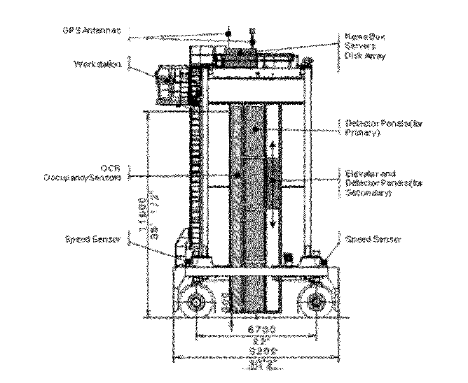
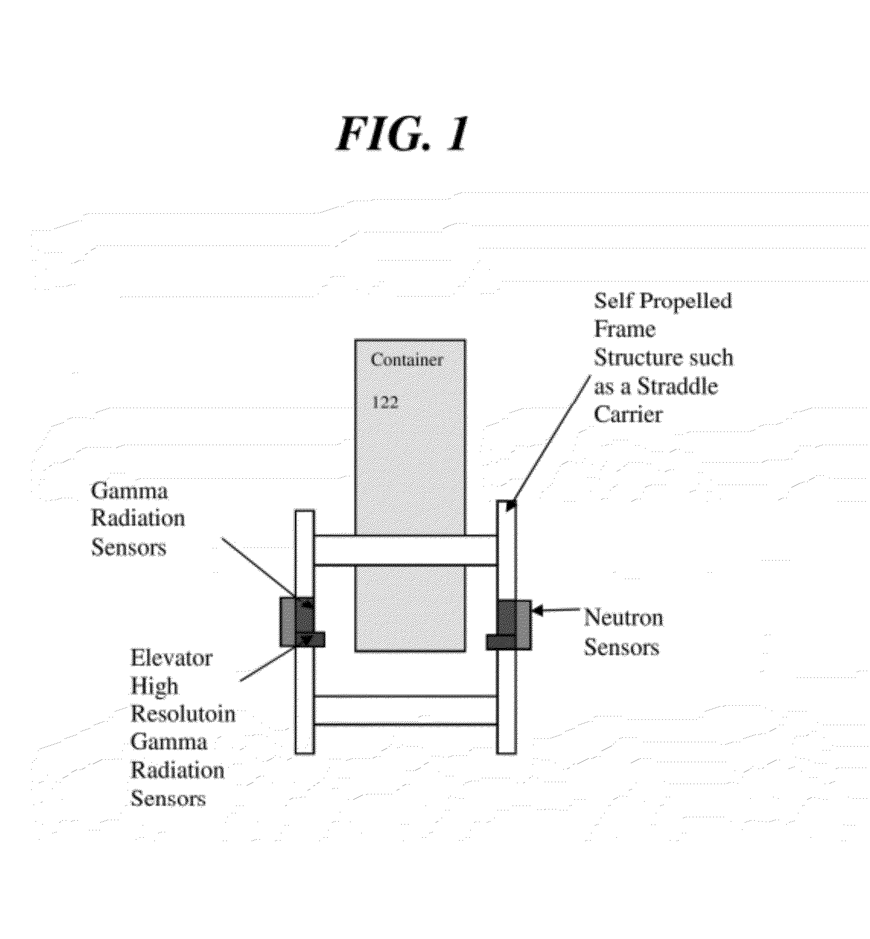
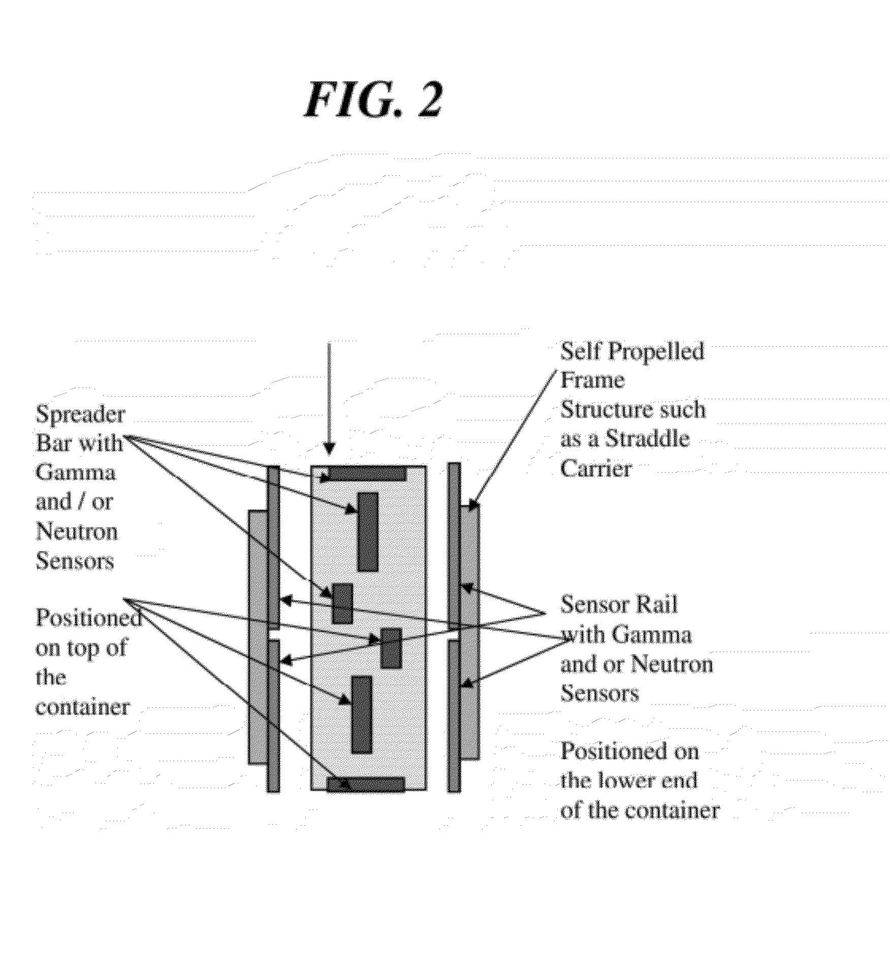
[0005]A high performance design for a straddle carrier, according to one embodiment of the present invention, provides detection and identification of radiation sources such as radioactive materials, gamma radiation emitting materials, and fissile materials. This embodiment of the present invention enables an efficient sensor configuration for a high sensor performance capability with moderate costs. The straddle carrier radiation verification system (SCRVS) provides highly accurate and sensitive non-invasive scanning of containers that are stacked 1, 2, 3 or 4 containers high in multiple columns and / or the scanning of a container during movement.
[0013]The use of an elevator system for the high resolution sensors reduces the need to deploy a large number of these costly sensors where they are needed. In other words, the use of the elevator system allows a concentrated number of high resolution sensors to be moved into position to perform a high speed and highly accurate analysis of an individual targeted container position in a stack of containers in a very cost effective manner.

Problems solved by technology

This design is extremely costly and inefficient with heavy materials used for collimation and large straddle carrier frames required to support the weight.
The costs of such systems are prohibitive for volume procurement and deployment.

Method used


Image

  • High performance straddle carrier cbrne radiation verification system
  • High performance straddle carrier cbrne radiation verification system
  • High performance straddle carrier cbrne radiation verification system

Examples


Embodiment Construction

[0032]As required, detailed embodiments of the present invention are disclosed herein. However, it is to be understood that the disclosed embodiments are merely examples of the invention, which can be embodied in various forms. Therefore, specific structural and functional details disclosed herein are not to be interpreted as limiting, but merely as a basis for the claims and as a representative basis for teaching one of ordinary skill in the art to variously employ the present invention in virtually any appropriately detailed structure and function. Further, the terms and phrases used herein are not intended to be limiting; but rather, to provide an understandable description of the invention.

[0033]The terms “a” or “an”, as used herein, are defined as one or more than one. The term plurality, as used herein, is defined as two or more than two. The term another, as used herein, is defined as at least a second or more. The terms including and / or having, as used herein, are defined as...


PUM


Abstract

A hazardous materials detection and identification system includes a set of distributed sensors across one or more sides of a self propelled frame structure such as a straddle carrier or similar cargo equipment device. The system non-invasively analyzes vehicles, one or more containers in a stack, a container during lift and movement, a package, cargo, or other objects, that are located in an analysis position relative to the self propelled frame structure for detection and identification of hazardous materials such as chemicals, biological materials, radiological materials, fissile materials, and explosives (CBRNE). The system includes one or more detector arrays that can be configured for various applications such as: shipping container inspection, seaport security, cargo terminal security, airport vehicle inspection, airport cargo inspection, airport baggage inspection, vehicle inspection, truck stop cargo inspection, border protection inspecting vehicles, cargo, persons, railway inspections, railcar inspection, and subway security.

Description

CROSS-REFERENCE TO RELATED APPLICATIONS[0001]This application is based on, and claims priority from, co-pending U.S. Provisional Patent Application No. 61 / 134,405, filed on Jul. 10, 2008, by inventor David L. FRANK, and entitled “High Performance Straddle Carrier CBRNE Radiation Verification System”; and also claims priority from co-pending U.S. Provisional Patent Application No. 61 / 183,185, filed on Jun. 1, 2009, by inventor David L. FRANK, and entitled “High Performance Straddle Carrier CBRNE Verification System”; and further is based on and claims priority to co-pending U.S. patent application Ser. No. 12 / 409,758, entitled “Horizontal Sensor Arrays For Non-Invasive Identification Of Hazardous Materials”, filed on Mar. 24, 2009, which is based on and claims priority to prior co-pending provisional U.S. Patent Application No. 61 / 070,560, entitled “Horizontal Sensor Arrays For Non-Invasive Analysis Of CBRNE Materials Present”, filed on Mar. 24, 2008, by the same inventor; and this a...

Claims


Application Information

Patent Timeline
Patent Type & Authority Applications(United States)
IPC IPC(8): G01T7/00
CPCG01T1/167G01V5/0083G01V5/0075
Inventor FRANK, DAVID L.
Owner INNOVATIVE AMERICAN TECH
Why Eureka
Try Eureka