Fluidproof connector

a technology of connectors and connectors, applied in the direction of couplings/cases, coupling device connections, securing/insulating coupling contact members, etc., can solve the problems of poor production efficiency, increased production costs of prior art connectors, and material leakage through clearances, etc., to achieve the effect of simple construction and work efficiency at the time of electrical connection

Inactive Publication Date: 2012-05-24
SUMITOMO WIRING SYST LTD
View PDF2 Cites 16 Cited by
  • Summary
  • Abstract
  • Description
  • Claims
  • Application Information

AI Technical Summary

Benefits of technology

[0021]The busbars may be arranged to face each other with the capacitor arranged between the busbars. Each busbar may include a cantilevered clamping piece. The capacitor main body may be clamped between the busbars by the respective clamping pieces arranged to face each other. According to this construction, the capacitor can be positioned between the busbars by a simple construction and work efficiency at the time of electrical connection by soldering, welding or the like can be improved.

Problems solved by technology

However, there is a possibility that the potting material will leak through clearances between busbars and the housing.
Thus, a production cost of the prior art connector may be increased due to a molding failure resulting from this possibility.
Further, the required steps of heating and curing the filled epoxy resin make production efficiency poor.
Additionally, the epoxy resin itself is expensive.

Method used


Image

  • Fluidproof connector
  • Fluidproof connector
  • Fluidproof connector

Examples


Embodiment Construction

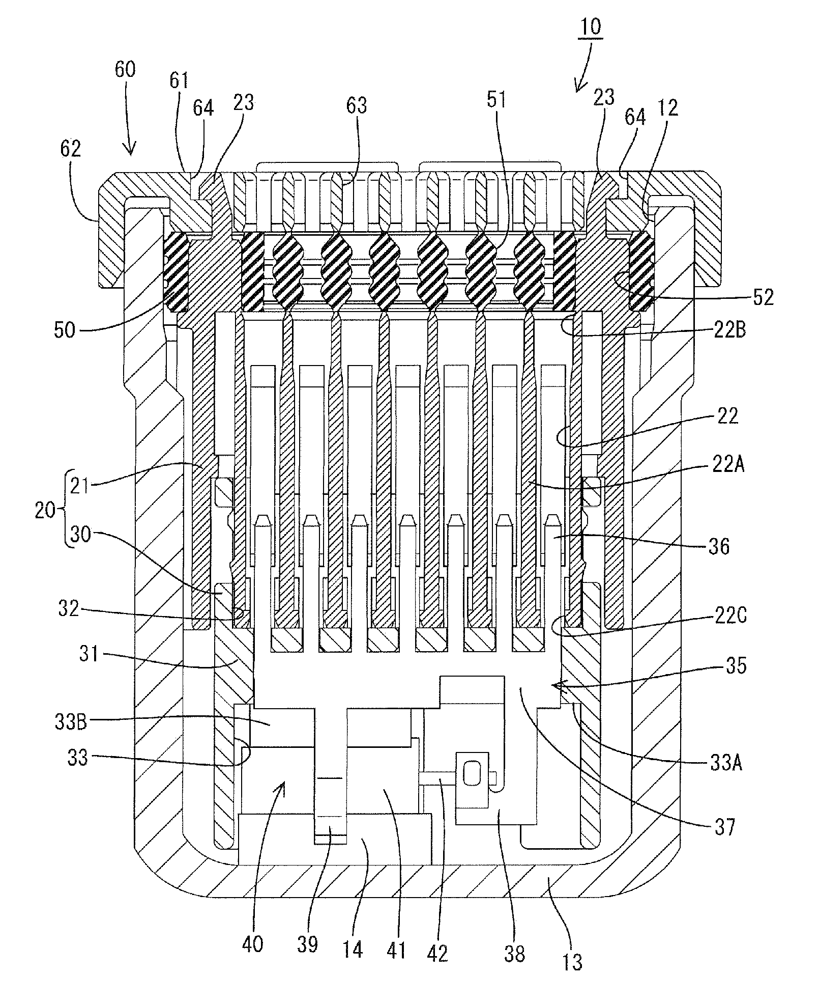
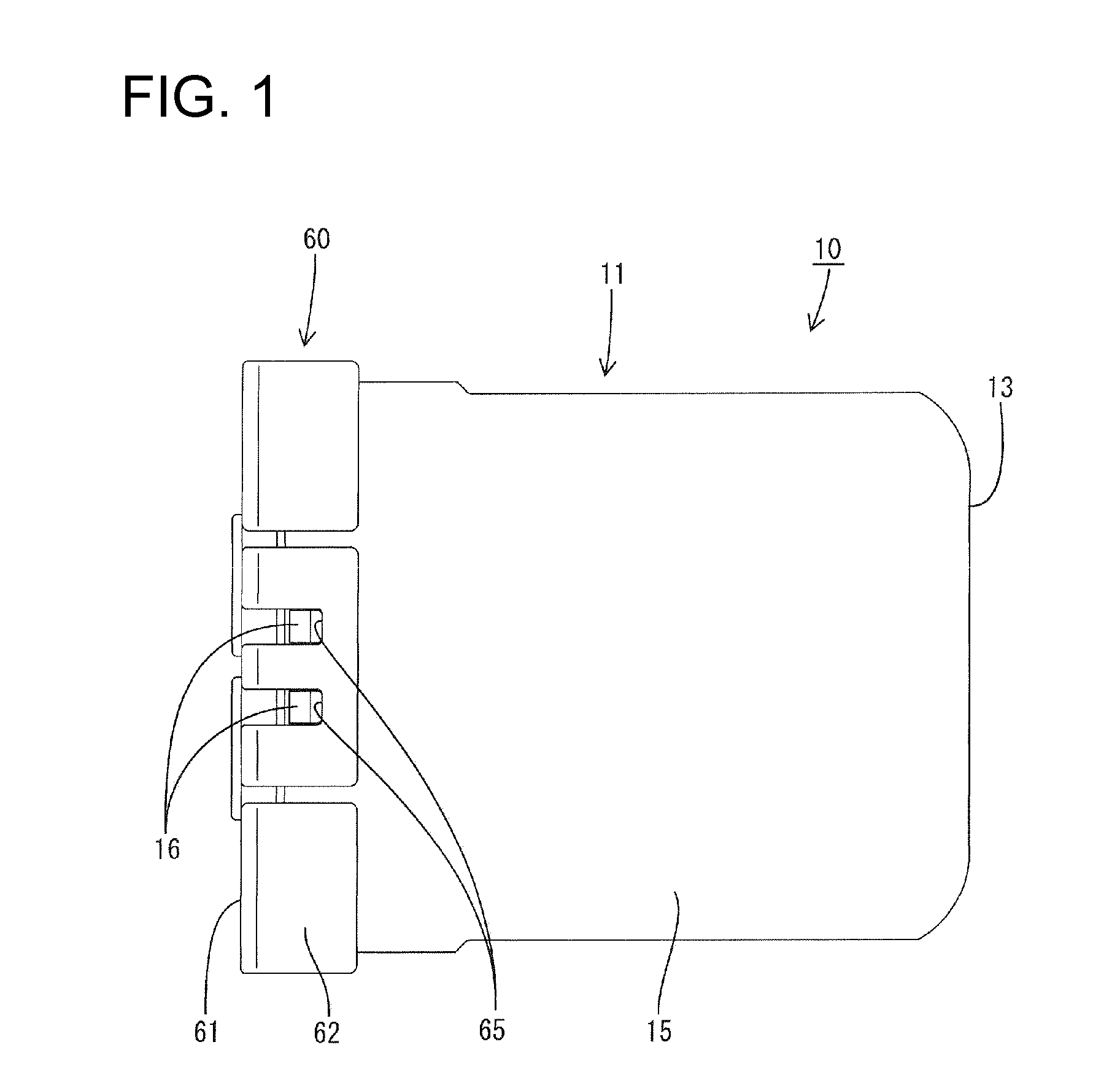
[0032]A waterproof connector in accordance with the invention is identified generally by the numeral 10 in FIGS. 1 to 4. The waterproof connector 10 includes an outer housing 11 with an opening 12 at one end and a bottom wall 13 opposite the opening 12. The end of outer housing 11 with the opening can be connected to a mating connector and is referred to herein as the front end. The end with the bottom wall 13 is referred to as a rear end.

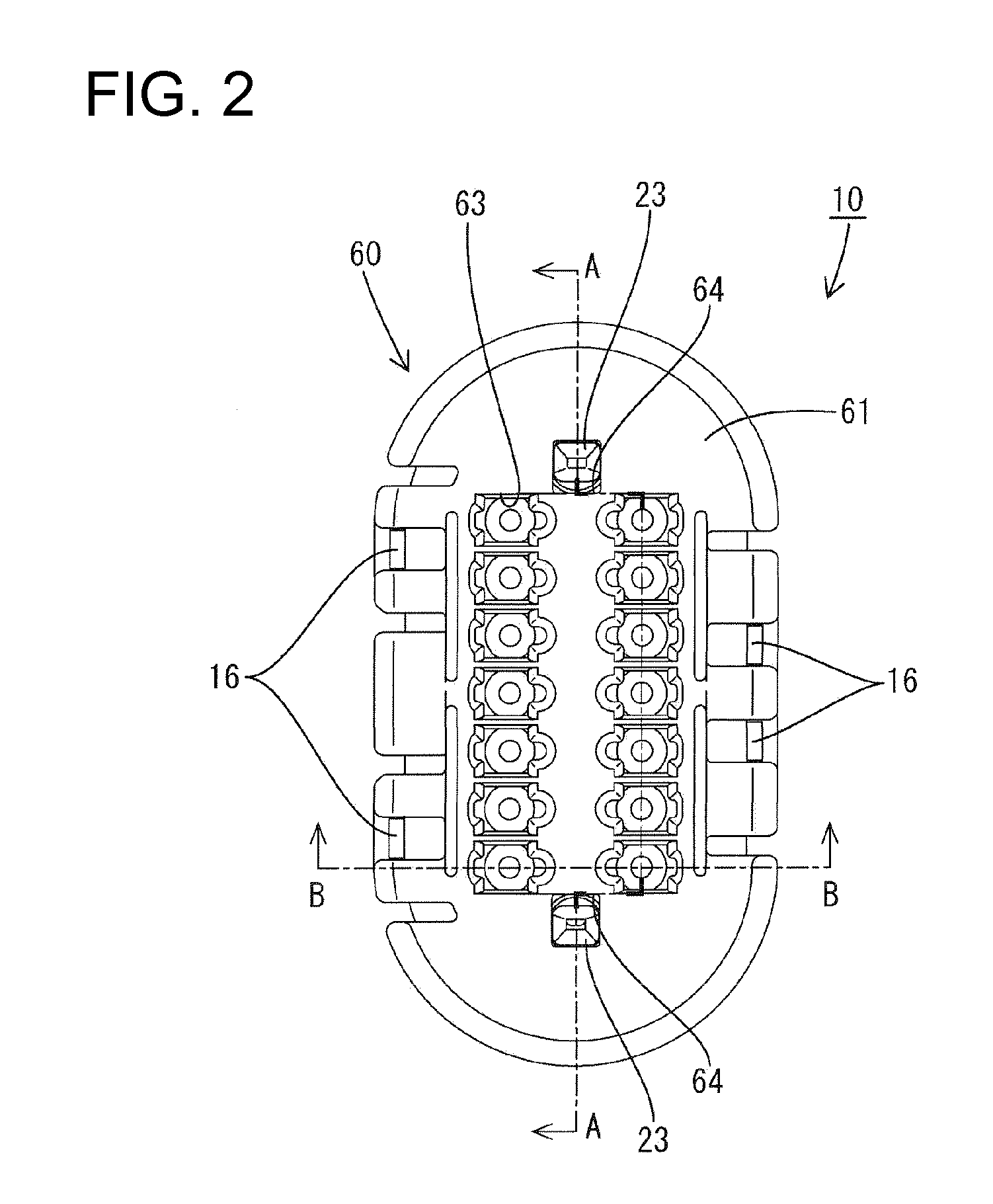
[0033]The outer housing 11 is made e.g. of synthetic resin and is substantially in the form of a bag or cup that is open only in one direction. The opening 12 has a substantially elliptical or rounded shape. A substantially block-shaped receiving portion 14 projects from the bottom wall 13 toward the opening 12. A side wall 15 extends unitarily from the bottom wall 13 and an end of the side wall 15 opposite the bottom wall 13 defines the opening 12. Locking projections 16 project from the side wall 15 near the opening 12.

[0034]The waterproof connec...


PUM


Abstract

A waterproof (10) is provided with a capacitor (40); two busbars (35) connected via the capacitor (40). Each busbar (35) includes tabs (36), a coupling (37) connecting the tabs (36), and a connecting portion (38) connected to an electrode of the capacitor (40). A housing (11) houses the busbars (35) and the capacitor (40) and is open only in one direction. The housing (11) holds the terminal fittings inserted through an opening (12) of the housing (11) to be connected to the tabs (36) of the busbars (35). A seal (50) is press-fit into the housing (11) through the opening (12) and has through holes (51) through which the wires are closely inserted. A holder (60) having wire insertion holes (63) corresponding to the through holes (51) is mounted to cover the opening (12) of the housing (11) to retain and hold the seal (50).

Description

BACKGROUND OF THE INVENTION[0001]1. Field of the Invention[0002]The invention relates to a fluid or waterproof connector with a built-in electric element or component, such as a capacitor.[0003]2. Description of the Related Art[0004]Japanese Unexamined Patent Publication No. 2007-287644 discloses a joint connector with a built-in capacitor. The joint connector is used for collectively connecting wires arranged in an automotive vehicle and includes flat busbars. Each busbar has terminal portions to be connected to the wires are connected like comb teeth. The busbars are connected via the capacitor. The capacitor is fixed by soldering after lead wires are inserted and positioned at through holes formed in the busbars.[0005]FIGS. 8 and 9 herein show a known waterproof connector 1 with a built-in capacitor. This connector 1 has a core 2 made of synthetic resin and busbars 3 are press-fit into the core 2. The connector 1 also has a capacitor 4 with lead wires 5 that are soldered to the b...

Claims


Application Information

Patent Timeline
Patent Type & Authority Applications(United States)
IPC IPC(8): H01R13/52
CPCH01R13/521H01R2201/26H01R13/6625H01R13/52
Inventor FUJISAKI, RYUICHI
Owner SUMITOMO WIRING SYST LTD
Why Eureka
Try Eureka