


Quick Research
Generate reliable direction feasibility study reports for your R&D in just a few steps.

Technical Q&A
Discover and master advanced knowledge NOW. Basics, ideas, possibilities, all at once.

Find Solutions
As an expert in R&D theories, this can generate solutions to your technical problems instantly.

Evaluate Feasibility
Analyze your overall solution with one click, know your potential R&D risks in advance.

Monitor Landscape
Get weekly tech updates, stay abreast of the latest tech innovations and key insights.
Laminate composite and method for making same
a laminate and composite technology, applied in the field of magnets, can solve the problems of poor properties and manufacturing methods, limited success, and hampered spintronics' pursuit,
- Summary
- Abstract
- Description
- Claims
- Application Information
AI Technical Summary
Benefits of technology
Problems solved by technology
Method used
Image

Examples
example 1
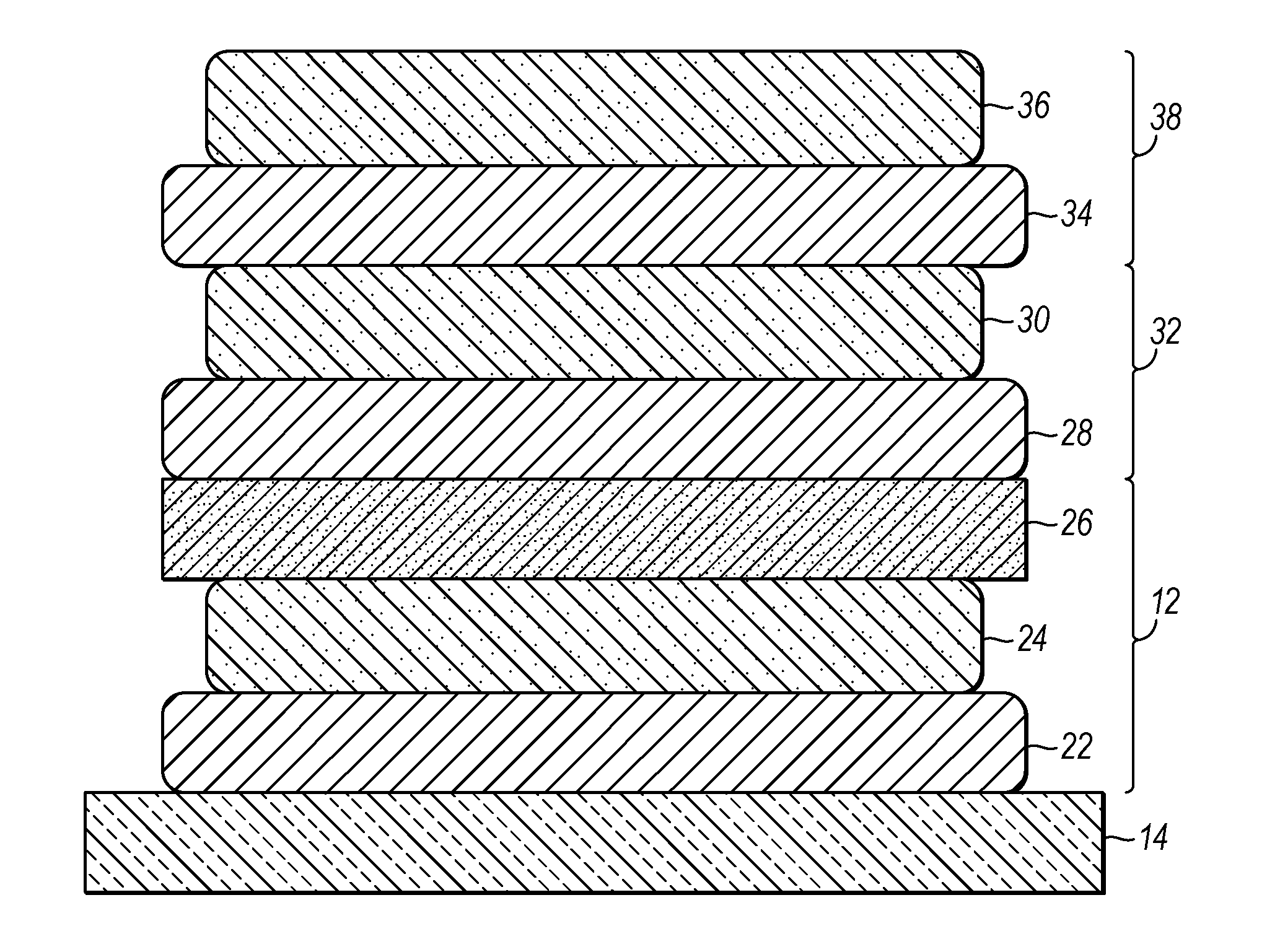
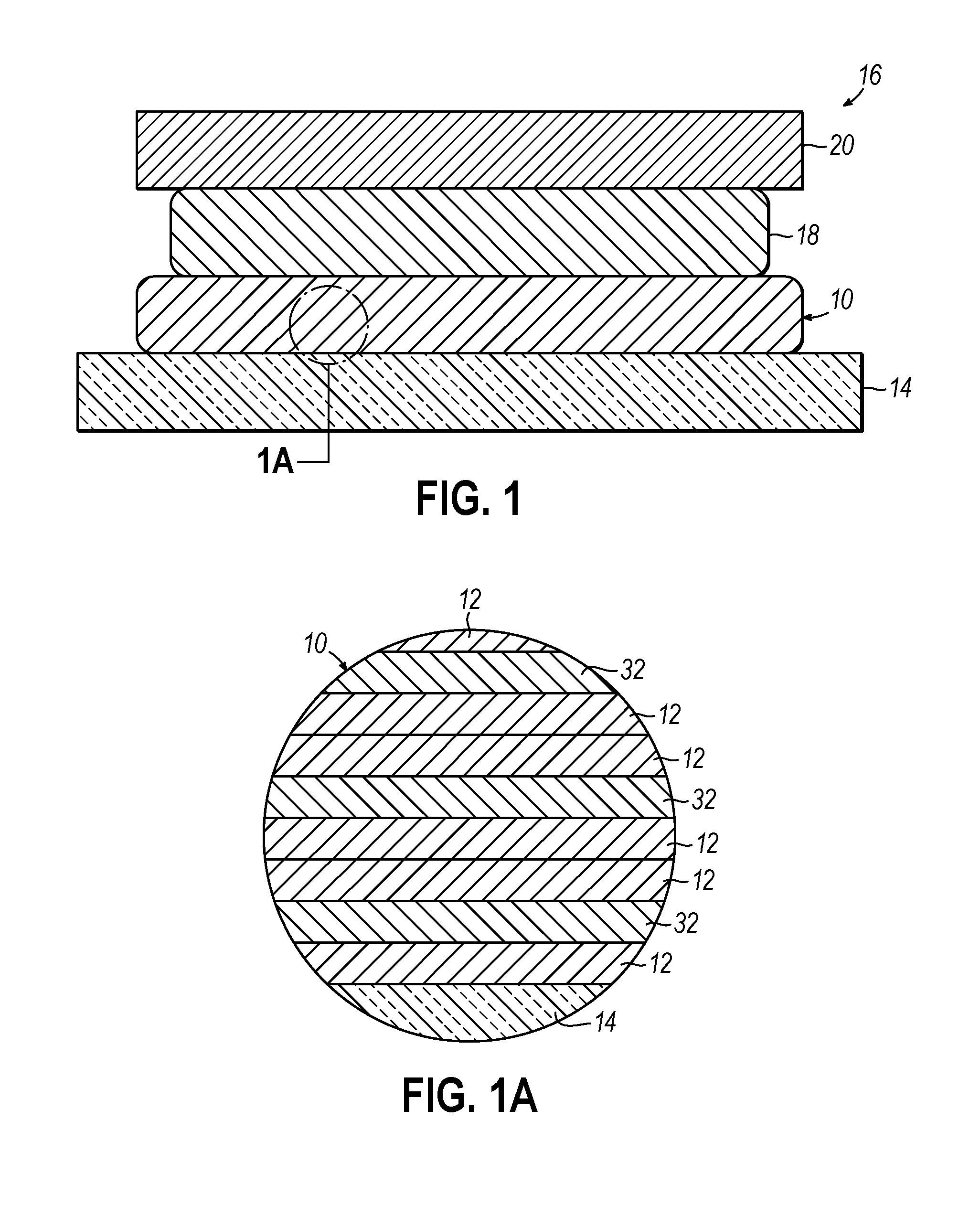
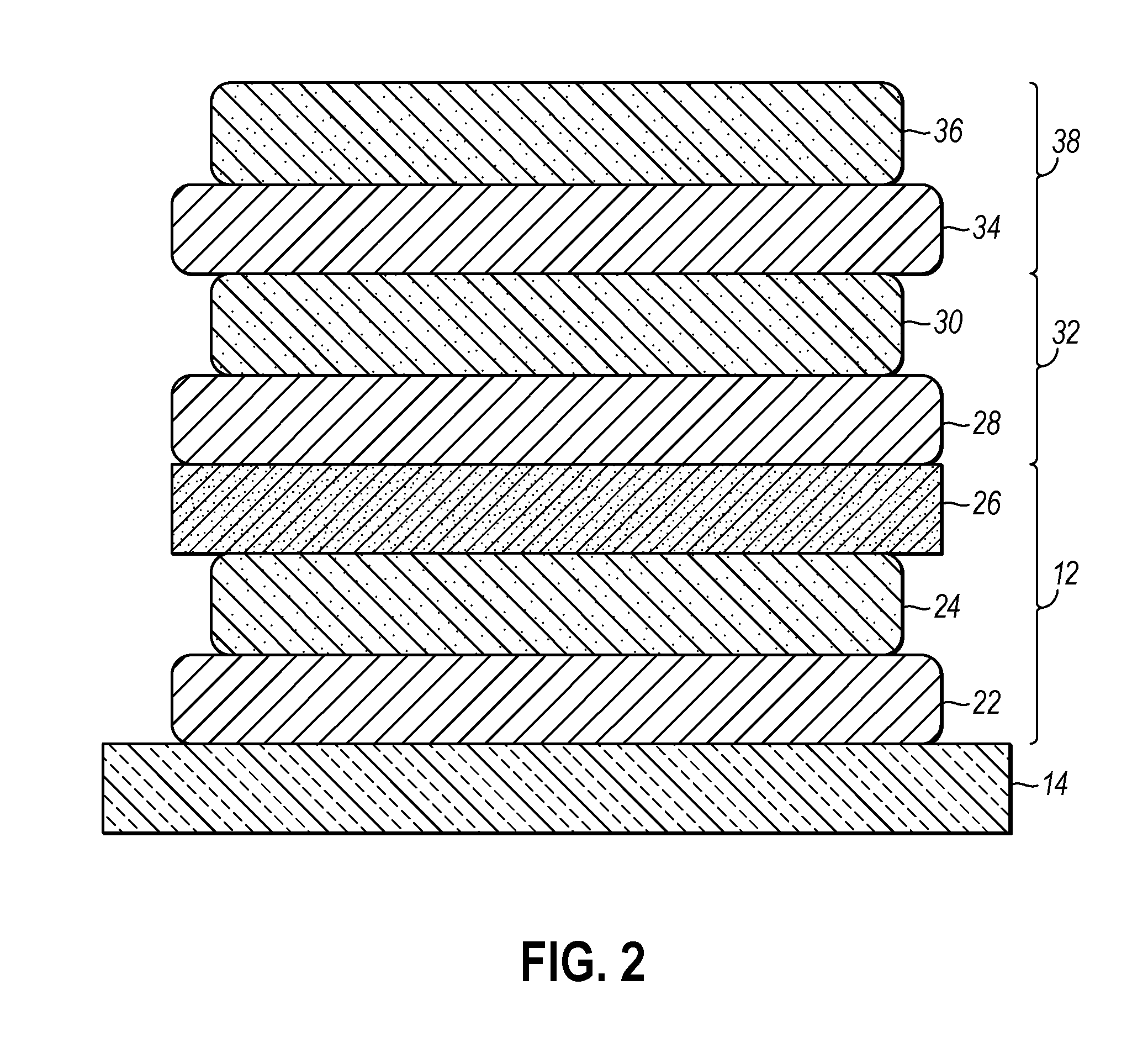
[0053]A V[TCNE]x laminate composite was formed on Si(111) wafers. A MLD device was utilized to deposit the laminate composite. The organic compound was TCNE from Sigma-Aldrich which was purified by sublimation with activated carbon before deposition. The metal-containing compound was V(CO)6 which was synthesized according to known principles. Both compounds were stored in air-tight containers in an inert environment in a refrigerator at a temperature of about 40° C.
[0054]During deposition, the base pressure in the main chamber was about 10−5 torr as a result of pumping the chamber overnight. The deposition was started by opening a shut-off valve between the main chamber and a precursor cell that contained the V(CO)6. The substrate was exposed to V(CO)6 for about 50 s to deposit V(CO)6. During V(CO)6 deposition, the pressure was permitted to rise to about 0.5 to 1 torr.
[0055]Following V(CO)6 deposition, the chamber was evacuated to remove excess V(CO)6 and reaction by-products, like ...
example 2
[0059]A Co[TCNE]x laminate composite was deposited on Si(111) wafers in a similar sequence with the same MLD device to that of Example 1. In Co[TCNE]x deposition, Co2(CO)8 was used. After the deposition, the chamber was then transferred into the Ar-filled glove box for measurement.
[0060]The growth process was monitored by QCM and the result is shown in FIG. 5. As shown, the mass of the layers progressively increases with multiple cycles. The thickness of the resulting film was about 26 nm for a deposition of 30 cycles. Atomic force microscopy (AFM) was used to measure the roughness of the laminate. The RMS roughness was measured at about 0.17 nm and the image is shown in FIG. 6.
example 3
[0061]A V-Co-TCNE laminate composite was deposited on Si(111) wafers in a similar sequence with the same MLD device to that of Example 1. In V-Co-TCNE deposition both Co2(CO)8 and V(CO)6 were used. The sequence for deposition was V(CO)6, TCNE, Co2(CO)8, TCNE, V(CO)6, TCNE, Co2(CO)8, TCNE, and so on. After the deposition, the chamber was then transferred into the Ar-filled glove box for measurement.
[0062]The growth process was monitored by QCM and the results are shown in FIGS. 10 and 11. As shown, the mass of the layers progressively increases with multiple cycles. Another mass gain plot is shown in FIG. 12 in which the mass gain per cycle is shown. The higher mass gain per cycle being during the deposition of Co[TCNE]. The magnetization of the V-Co-TCNE laminate composite as a function of applied magnetic field and measured parallel to the longitudinal axis of the composite is shown in FIG. 13. Of the overlapping hysteresis, one is at 5 K and the other is at 300 K as is indicated i...
PUM
| Property | Measurement | Unit |
|---|---|---|
| aspect ratios | aaaaa | aaaaa |
| thickness | aaaaa | aaaaa |
| coercivity | aaaaa | aaaaa |
Abstract
Description
Claims
Application Information
 - R&D Engineer
- R&D Manager
- IP Professional
- Industry Leading Data Capabilities
- Powerful AI technology
- Patent DNA Extraction
Browse by: Latest US Patents, China's latest patents, Technical Efficacy Thesaurus, Application Domain, Technology Topic, Popular Technical Reports.
© 2024 PatSnap. All rights reserved.Legal|Privacy policy|Modern Slavery Act Transparency Statement|Sitemap|About US| Contact US: help@patsnap.com