
Keycard and keycard-lock

a keycard and keycard technology, applied in the field of keys/lock systems, can solve the problem of not being able to know who enters the premises or the room

Inactive Publication Date: 2012-05-24
INT FRONTIER TECH LAB
View PDF16 Cites 2 Cited by
  • Summary
  • Abstract
  • Description
  • Claims
  • Application Information

AI Technical Summary

Benefits of technology

"The patent text describes a keycard and keycard-lock system that can be used to identify who enters a premises or room. The keycard contains information that is encrypted and decrypted using a crypt key stored in the lock. The keycard can be read from various directions and is housed in a cassette to prevent damage. The technical effects of this invention include improved security and access control for restricted areas."

Problems solved by technology

In a facility where plural relevant parties come in and out, when entering the premises or a room needs to be restricted, such measures are taken as preparing plural keys or using a password; however, with such measures, it is not possible to know who enters the premises or the room.

Method used


Image

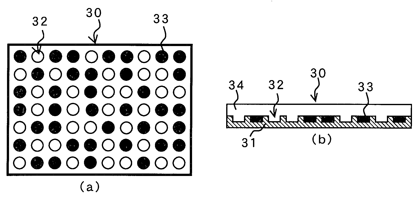
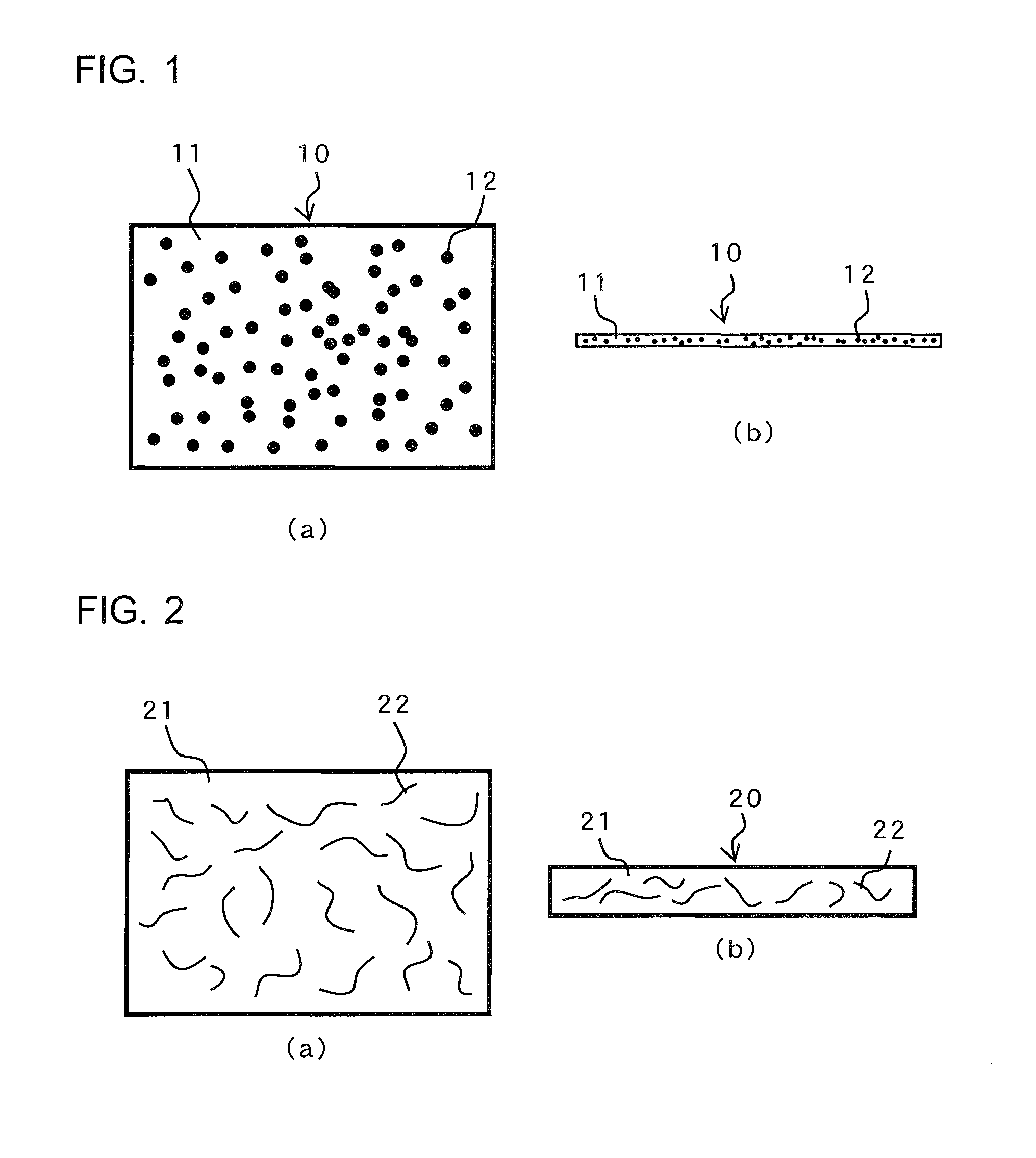
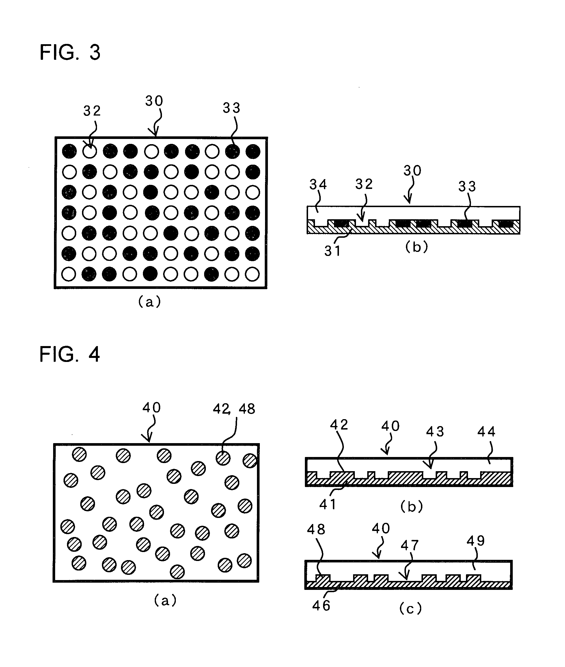
  • Keycard and keycard-lock
  • Keycard and keycard-lock
  • Keycard and keycard-lock

Examples


embodiment 1

[0119]FIG. 13 shows a keycard. FIG. 13 (a) shows a general view of a keycard of Embodiment 1 in which a keycard information chip is mounted on a portion thereof and FIG. 13 (b) a cross-sectional view.

[0120]On a keycard 130, a keycard information chip 132 is non-removably mounted at the center of a surface plate 133 attached to a substrate 131.

[0121]In the mounting configuration shown here, the small keycard information chip 132 is placed at the center of the surface plate 133, while the mounting position and the size of the keycard information chip 132 are not limited to this example, and various positions may be possible.

embodiment 2

[0122]While the keycard 130 shown in FIG. 13 has the small keycard information chip 132 placed at the center of the surface plate 133, the entire surface of a keycard 140 shown in FIG. 14 is a keycard information chip, in other words, the keycard itself serves as a keycard information chip. Therefore, the security of the keycard is improved.

[0123]FIG. 14 (a) shows a general view of a keycard and FIG. 14 (b) a cross-sectional view.

[0124]On a keycard 140, thin iridescent pieces 142, 143, 144 which constitute an information pattern are embedded at random positions in a transparent resin 145 which covers the entire surface of a substrate 141.

[0125]For the reading of the information pattern, the entire surface of the keycard 140 may be read.

embodiment 3

[0126]Since the keycard information chip of the card described in FIGS. 1 to 12 has optical information except for radioactive substance granules shown in FIG. 7, the resistance properties against damages and stains on the card surface are low.

[0127]Since a card used as a key is often placed in a pocket or a bag not in order, the risk of damaging and staining is high.

[0128]Accordingly, the keycard information chip that is to be read is protected by a shutter.

[0129]FIG. 15 shows an example in which a shutter opening sideways is adopted.

[0130]FIGS. 15 (a) and (c) show when the shutter is closed while the keycard is not in use, FIGS. 15 (b) and (d) show when the shutter is opened while the keycard is in use, and FIGS. 15 (c) and (d) are cross-sectional views.

[0131]FIG. (e) is an exploded view of elements constituting the keycard.

[0132]A keycard 150 includes a keycard body 151, a container 152 having a housing 156 for the keycard body 151, a cover plate 155 in which a window 154 for rea...


PUM


Abstract

To acquire a keycard, the creation of whose clone is impossible, and a keycard-lock that is locked / unlocked by the keycard.Key information constituted by randomly disposed metal granules, fiber pieces, a hologram chip, fluorescent substance granules, radioactive substance granules, or iridescent material, which is obtained by chance, is provided to a card. By inserting the keycard into the keycard-lock, and storing data based on the key information of the keycard in the keycard-lock, the keycard is registered in the keycard-lock. The data is encrypted by using a crypt key stored in the keycard-lock. By comparing the data of keycard inserted into the keycard-lock and the data obtained by decrypting the encrypted data registered in the keycard-lock, the keycard-lock is locked / unlocked. In addition, data based on the information of the keycard is encrypted and stored in a self-certifying keycard information chip installed in the keycard.

Description

FIELD OF THE INVENTION[0001]The present invention according to this application generally relates to a key / lock system for locking / unlocking using a keycard having the shape of a card, and in particular, to a keycard used in an immobiliser system adopted for vehicles for theft-prevention purposes, and a keycard-lock which is locked / unlocked by the keycard.BACKGROUND ART[0002]Since mechanical keys having the shape of so-called keys require thickness, they are not considered so handy for carrying around. As a countermeasure, keycards fitting the shape of credit cards or the like are becoming widely used. The keycard has mechanical information, magnetic information, data stored in an IC chip and the like, in a card-shaped body constituted from various materials, and the lock determines whether or not to do the lock / unlock operation.[0003]Immobiliser systems for vehicle theft-prevention purposes are becoming more common. In these immobiliser systems, a computer on the vehicle side deter...

Claims


Application Information

Patent Timeline
Patent Type & Authority Applications(United States)
IPC IPC(8): G06K5/00B60R25/04B60R25/24
CPCE05B35/007G06K19/083G07C2009/00976G07C9/00G07C9/00944G06K19/086
Inventor KOMATSU, NOBUAKINANJO, SHIN-ICHIRO
Owner INT FRONTIER TECH LAB
Learn More