Alkaline storage battery electrode and alkaline storage battery
- Summary
- Abstract
- Description
- Claims
- Application Information
AI Technical Summary
Benefits of technology
Problems solved by technology
Method used
Image
Examples
first embodiment
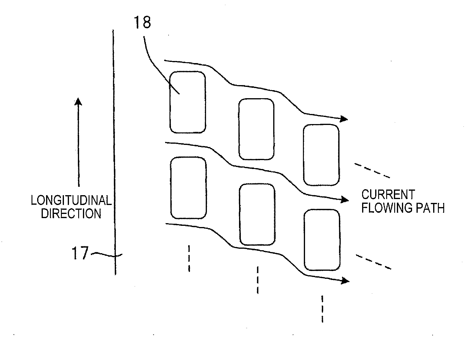
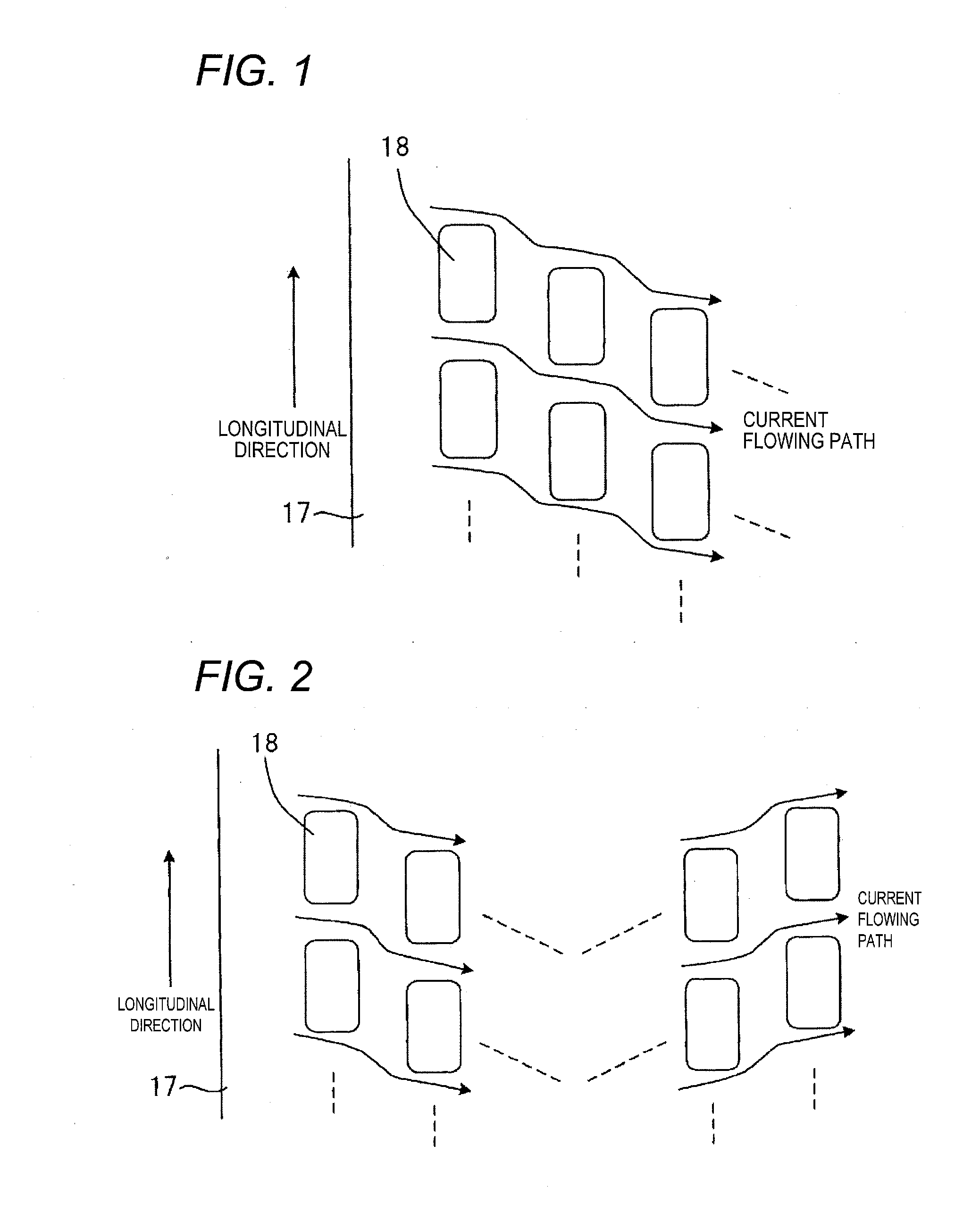
[0046]FIG. 1 is a developed view of core member 17 used in an alkaline storage battery electrode according to a first embodiment of the invention. Many substantially rectangular through holes 18 are provided in the core member 17 of a belt shape. The core member 17 is coated with paste containing active material such as hydrogen absorbing alloy thereby forming the alkaline storage battery electrode. In this embodiment, the through holes 18 are disposed linearly in parallel with the longitudinal direction of the core member 17. Each of the through holes 18 is formed in a substantially rectangular shape. Lines of the through holes 18 are arranged so as to be sequentially shifted in the longitudinal direction of the core member 17.
[0047]In the case of forming the substantially rectangular through hole of the core member, similar to the example of related art shown in FIG. 19, the through holes are generally arranged such that the adjacent lines are disposed in a staggered pattern along...
second embodiment
[0054]FIG. 2 is a developed view of core member 17 used in an alkaline storage battery electrode according to the second embodiment of the invention. The second embodiment shows an example of the configuration where the displacement amount x of the through holes 18 is set to both opposite directions in the longitudinal direction of the core member 17. In the example of FIG. 2, arrangements in which the displacement amount of the through holes 18 is set to the lower direction so as to shift obliquely to the right downward direction are repeated for a predetermined number of times, and then arrangements in which the displacement amount of the through holes 18 is set to the upper direction so as to shift obliquely to the right upward direction are repeated for a predetermined number of times. In this case, the direction of the displacement amount x of the through holes 18 in the longitudinal direction of the core member 17 is changed to the opposite direction on the way, thereby arrang...
example 1
[0072]FIG. 5 is a diagram showing the arrangement of the through holes of the core member in the example 1 of this invention. As the core member 17 of the negative electrode plate 12, a nickel-plated steel plate (thickness of 60 μm) was used by perforating the through holes 18 each having the substantially rectangular shape with an opening area of 2.0 mm2. The width of the core member 17 was set to 50 mm. To be concrete, as shown in FIG. 5, the through holes 18 were arranged in the core member 17 in a manner that the size “a” of the through hole in the longitudinal direction of the core member was set to 2.0 mm, the distance “b” between the adjacent through holes in the longitudinal direction of the core member was set to 1.0 mm, the size “c” of the through hole in the width direction of the core member was set to 1.0 mm, the distance “d” between the adjacent through holes in the width direction of the core member was set to 0.5 mm, and the displacement amount x of the through holes...
PUM
 Abstract
Description
Claims
Application Information
 - R&D
- Intellectual Property
- Life Sciences
- Materials
- Tech Scout
- Unparalleled Data Quality
- Higher Quality Content
- 60% Fewer Hallucinations
Browse by: Latest US Patents, China's latest patents, Technical Efficacy Thesaurus, Application Domain, Technology Topic, Popular Technical Reports.
© 2025 PatSnap. All rights reserved.Legal|Privacy policy|Modern Slavery Act Transparency Statement|Sitemap|About US| Contact US: help@patsnap.com


