
Monitoring system of computer and monitoring method

a computer and monitoring system technology, applied in the field of monitoring systems of computer systems, can solve the problems of taking a time (data volume and table generation cost) of o(ssup>2/sup>) times each, and achieve the effect of improving the efficiency of operations management, reducing the cost required, and shortening the tim

Inactive Publication Date: 2012-05-10
HITACHI LTD
View PDF11 Cites 155 Cited by
  • Summary
  • Abstract
  • Description
  • Claims
  • Application Information

AI Technical Summary

Benefits of technology

[0017]In order to solve problems of the technological background and the prior art described above, it is necessary to make operational conditions of physical resources that the virtual servers share easily analyzable by acquiring history management of the configuration information of the computer system and the performance statistics and associating the history of the configuration information, the performance statistics, and the configuration information. Furthermore, there is a problem of reducing a cost at the time of configuration change, such as addition and deletion of the virtual server.
[0018]Then, the object of the present invention is to enable the relationships of computer resources that a virtual server uses to be represented in a tree structure without omission, and to enable the performance statistics of the virtual resources that share physical resources to be automatically aggregated in a monitoring system that displays relation between the configuration information and the performance statistics of the computer system.
[0020]Therefore, according to the present invention, it becomes possible to manage the relationship between virtual server and the base resources that the virtual server uses without omission and using a small amount of time. Furthermore, it becomes possible to analyze a situation of utilization of an arbitrary component for each virtual server from the performance statistics about the operation. Moreover, it becomes possible to navigate an efficient view of the performance statistics by the user analyzing the performance statistics according to the tree structure. By these capabilities, it is possible to shorten a time required to detect a bottleneck of the computer resources from the performance information and to improve an efficiency of the operations management in an environment where the computer system is equipped with a large number of computers.
[0021]In comparison with the above-mentioned Japanese Unexamined Patent Application Publication (Translation of PCT application) No. 2007-524889, the present invention outputs the configuration information by the tree structure. Therefore, a cost required for addition and deletion does not depend on the number of the servers and varies only for a portion to which the servers are related. Consequently, they can be executed at a cost of O(1). Here, designating the number of servers by S, since the data volume is proportional to the number of servers, the cost becomes O(s); therefore, it is possible to reduce the cost required for management and the data volume, as compare with the above-mentioned conventional technology.

Problems solved by technology

Under this precondition, when the relationship between system components was managed with a table, there was a problem of taking a time (data volume and a cost of table generation) of O(S2) times each time change of the virtual server was made.

Method used


Image

  • Monitoring system of computer and monitoring method
  • Monitoring system of computer and monitoring method
  • Monitoring system of computer and monitoring method

Examples


Embodiment Construction

[0067]Hereafter, one embodiment of the present invention will be explained based on accompanying drawings.

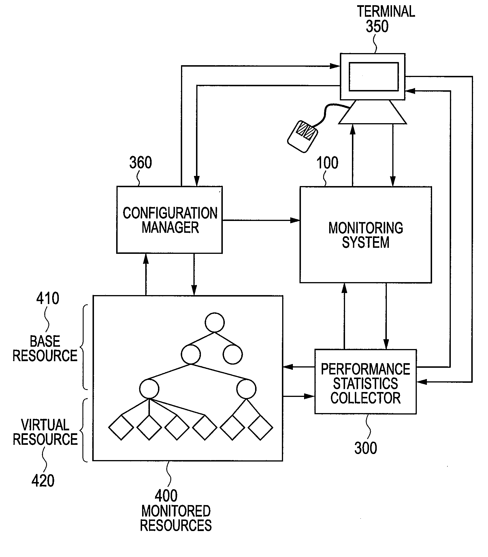
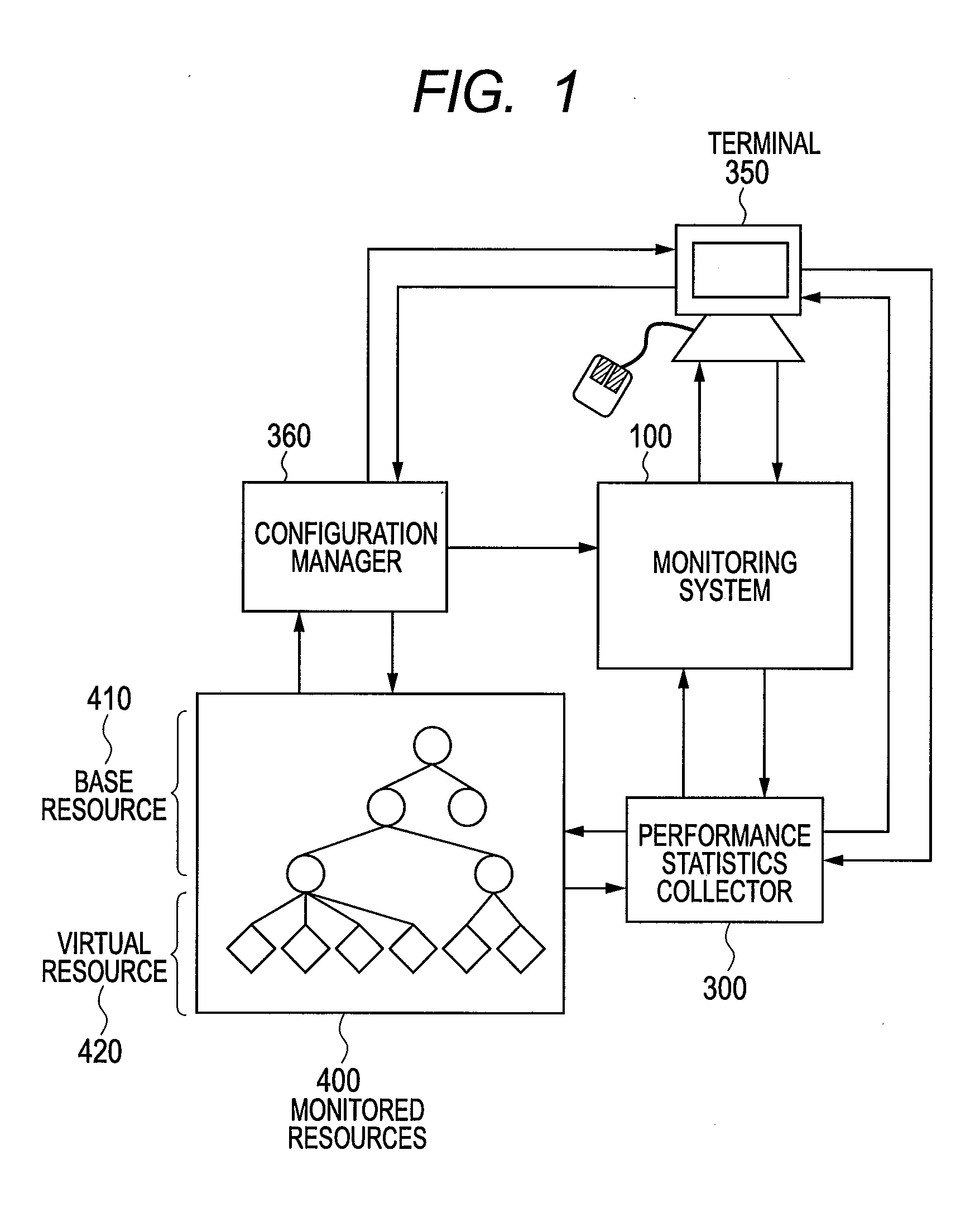
[0068]FIG. 1 shows a first embodiment and is an overall block diagram of a computer system including a computer monitoring system to which the present invention is applied. The computer system includes: a computer resource that becomes a monitored object (hereafter, referred to as a monitored resource) 400; a monitoring system (a monitoring apparatus) 100; a performance statistics collector 300; a configuration manager 360 for managing a configuration of the monitored resources 400; and a terminal 350 for referring to information that the monitoring system 100 collected.

[0069]The monitored resources 400 include base resources 410 that include a rack, a physical server (physical computer), a storage, and software (the hypervisor or the virtual machine monitor) for virtualizing resources of a network and the physical servers (physical resources), and virtual resources 420, such as...


PUM


Abstract

There is provided a monitoring system capable of representing relationships of computer resources that virtual servers use in a tree structure and aggregating the performance statistics of the virtual resources sharing physical resources. The monitoring system has: a virtualization module that makes virtual computers operate; and a monitoring module for monitoring the physical computers and components of the virtual computers. The monitoring module designates the physical computer and the components of the virtualizing module as base resources, manages the components of the virtual computers as virtual resources, generates a platform tree by extracting a tree structure from the virtual resources and the components of the base resources for predetermined platforms, generates a service provision tree by extracting a tree structure having the base or virtual resources as starting points, and establishes a reference relationship for the components contained in the platform tree and also contained in the service provision tree.

Description

CLAIM OF PRIORITY[0001]The present application claims priority from Japanese patent application JP 2010-248253 filed on Nov. 5, 2010, the content of which is hereby incorporated by reference into this application.FIELD OF THE INVENTION[0002]The present invention relates to a monitoring system of a computer system that includes multiple physical resources and multiple virtual resources.BACKGROUND OF THE INVENTION<Trend of Business World in Operations Management>[0003]In data centers that operate computer systems or the like, there are increasing vendors each of which supports or is planning to support description of management information, such as of network apparatuses, storage devices, server machines, OS, and server virtualization software in an XML format. Furthermore, a trend in which exchange of management information between apparatuses and between operation software is performed with an XML format file is also increasing.[0004]As a standardized specification of these pi...

Claims


Application Information

Patent Timeline
Patent Type & Authority Applications(United States)
IPC IPC(8): G06F15/173
CPCH04L41/0266G06F9/5077H04L41/5041H04L41/40
Inventor TANAKA, TSUYOSHIUEHARA, KEITAROKAWAMOTO, SHINICHI
Owner HITACHI LTD
Learn More