
Schlieren type ultrasonic wave observer system

a technology of ultrasonic wave and observer system, which is applied in the field of schlieren type ultrasonic wave observer system, can solve the problems of unfavorable general price, unfavorable carrying of system, and high cost of optical components, so as to increase the thermal treatment position accuracy, control the precise time delay of single chip, and increase the field of vision

Inactive Publication Date: 2012-05-10
CHANG GUNG UNIVERSITY
View PDF10 Cites 15 Cited by
  • Summary
  • Abstract
  • Description
  • Claims
  • Application Information

AI Technical Summary

Benefits of technology

[0020]The purpose of the invention is to provide a Schlieren type ultrasonic wave observer system, in order to observe the Schlieren and raise the performance of ultrasonic wave measurement.
[0022]As for the design of light route, the invention uses the optical field focusing lens to form the image on the charge-coupled device directly. Thus, the secondary imaging via lens is not required, the optical signal can be increased, and the Schlieren comparison of sound field will be more obvious.
[0023]In the whole optical structure, the invention uses the setup angle and match of spectroscope and reflector to increase the optical field of vision by several folds. It even is able to increase the quantity of spectroscopes to expand the vision of optical field infinitely in accordance with the actual requirement.
[0024]The beam expansion optical field of the invention adopts the spectroscope and the reflector, which can reduce the whole cost, and can benefit the commercialized development.
[0028]The characteristic of the invention is to use the spectroscope and the reflector combination to control precise time delay of single chip. It is able to increase the field of vision by several folds under the limit of conventional 4F optical field length.
[0029]The invention is suitable to collect full ultrasonic wave focusing information, thus it is favorable to observe the sound field distribution after the ultrasonic wave piercing through the foreign object (such as skull, rib, biological tissue). When the ultrasonic wave is piercing through the foreign object, if the focusing position can be observed in advance, the accuracy of thermal treatment position can be increased.

Problems solved by technology

However, due to too many optical components and the limitation of lens focus, the system will be bulky and unfavorable to be carried.
The optical components are very expensive, and it is very difficult to be made.
Thus, the price can not be born generally, and the bigger lens is often unable to be customized.
Thus, the vision of generated image will be limited, and full ultrasonic wave image will be unable to be obtained in a time.
When the full ultrasonic wave sound field is observed, it is necessary to carry out two times of photographing, which will increase the difficulty of photographing.
In the prior art such as U.S. Pat. No. 4,681,437, although a set of optical Schlieren system was established and the technology for installing Schlieren apparatus was proposed, no advanced recommendations were described for the size and application of optical field of vision.
Thus, summarized from the above-mentioned description, the drawbacks of previous art include:1. The conventional optical Schlieren measurement system is bulky, and it is not portable, thus it is unfavorable for the development of commercialized product.2. The optical field of vision is limited, thus it is unable to observe the full flow field at a time.3. When the optical field is expanded, the bigger lens has to be procured.
It will increase the manufacturing cost and the difficulty of customization.
Thus it is unfavorable for general commercialized development.4. It is unable to carry out the synchronous time sequence and it does not have the adjustable micro-control single chip core technology.

Method used


Image

  • Schlieren type ultrasonic wave observer system
  • Schlieren type ultrasonic wave observer system
  • Schlieren type ultrasonic wave observer system

Examples


Embodiment Construction

[0048]The invention relates to a Schlieren type ultrasonic wave observer system and application method thereof, and further increase the measurement efficiency.

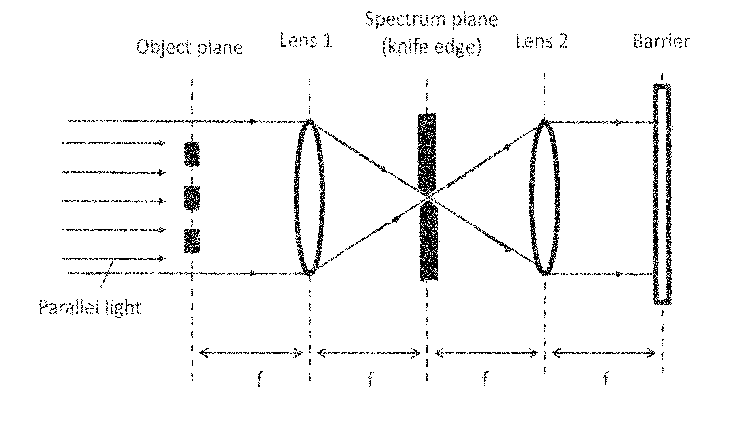
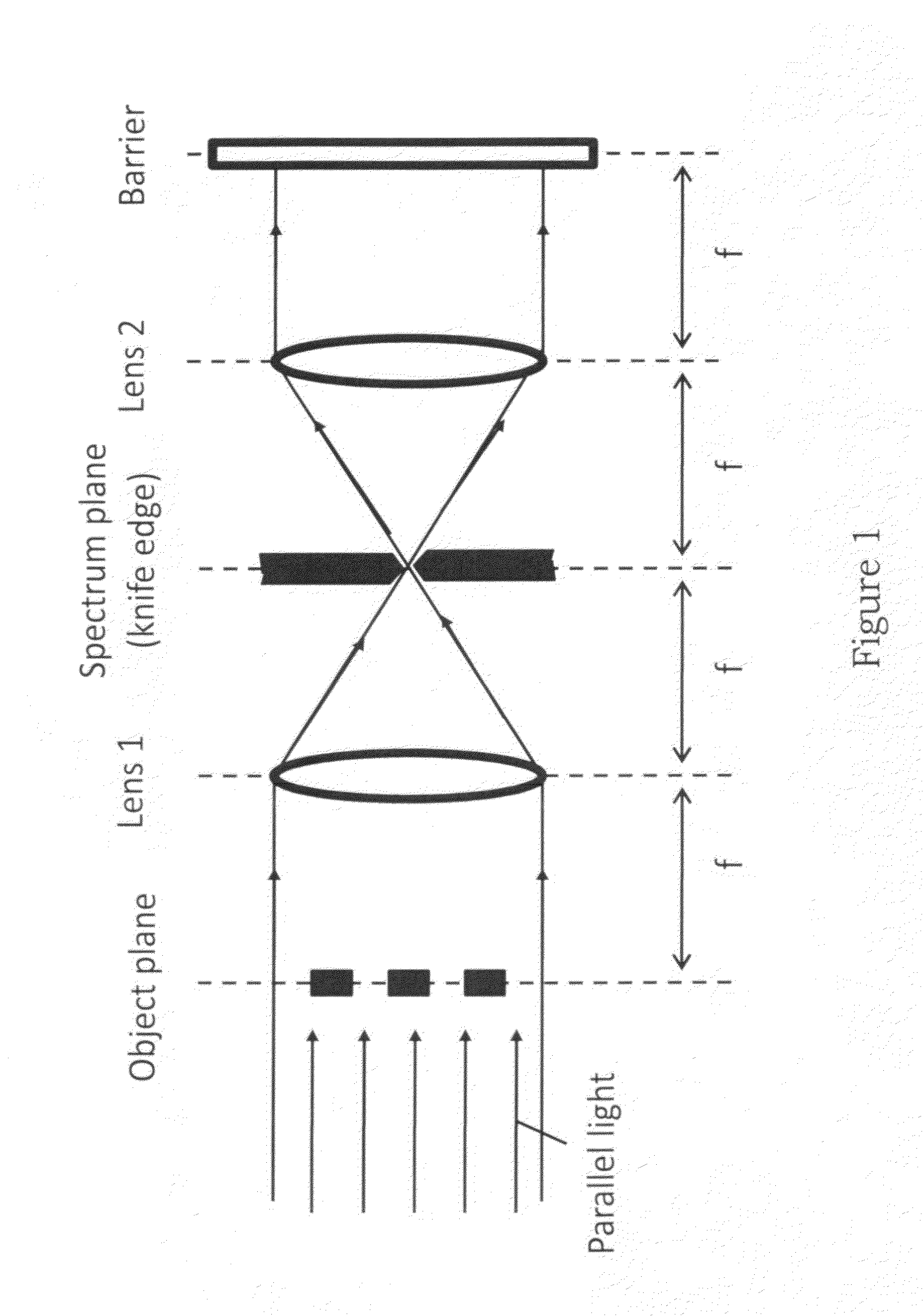
[0049]FIG. 3 shows the principle of 3-fold focus (3F) system of the invention. The system can use 3-fold focus to show the Schlieren effect, even have stronger image contrast. As shown in FIG. 3, the invention uses the space filter and beam expander to disperse the laser beam into the parallel light. After the parallel light pierces the object plane, the 1-fold focus is obtained. When the collected image is converged by a lens, the 2-fold focus is obtained. Finally, when the focusing image is shown on the barrier, the 3-fold focus is obtained.

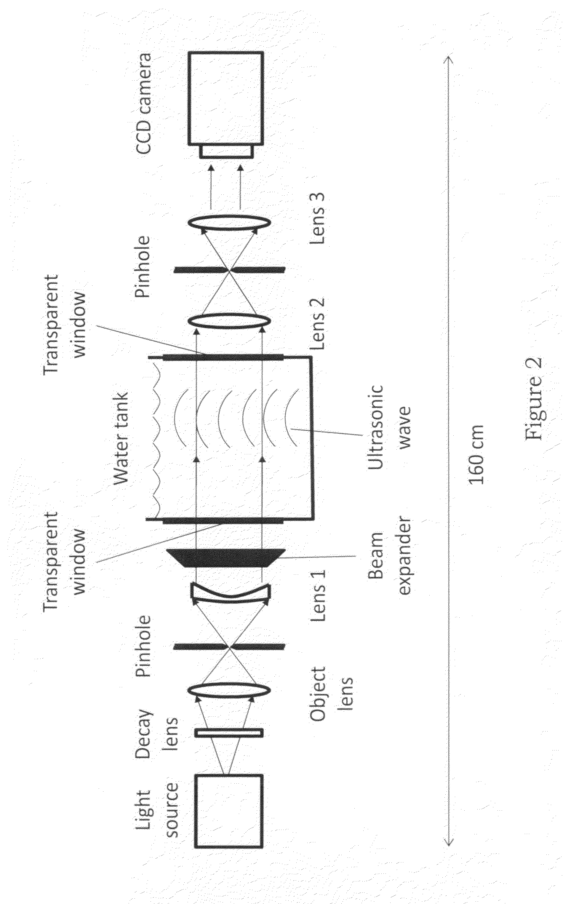
[0050]FIG. 4 shows the optical part for the Schlieren type ultrasonic wave observer system of the invention. It comprises a continuous wave laser 401, followed by decay lens 402, objective lens 403, pinhole 404 (the objective lens 403 and pinhole 404 can be combined to the so-called spac...


PUM


Abstract

The invention discloses the Schlieren type ultrasonic wave observer system. The invention states optics interference by the ultrasonic wave sound field after perturbation the medium, and combines to make the interference penetration optical projection the image, the goal lies in the observation ordinary naked eye blind ultrasonic wave sound field distribution. Characteristic of the invention using the spectroscope and the reflector combination, as well as microcontroller precise time delay control, might formerly be limited under the 4F optical field length limit to enhance largely the field of vision the several fold.

Description

BACKGROUND OF THE INVENTION[0001]1. Field of the Invention[0002]The invention relates to a Schlieren type ultrasonic wave observer system, particularly to a Schlieren type ultrasonic wave optical observer system.[0003]2. Description of the Prior Art[0004]The Schlieren phenomenon was found by the U.K. inventor (Robert Hooke) first in 1665. Afterward the German scientist (August Joseph Ignaz Toepler) manufactured the first Schlieren photography apparatus in the world.[0005]As for the technological principle of so-called Schlieren photography apparatus, because the light pierces through the transparent medium with uneven density, the advance direction of pierced light beam will be refracted due to the refractive index of transparent medium is changed with density. Thus, the Schlieren photography apparatus utilizes the perturbation of fluid on the light wave to present the geometrical shape and concentration at the place with uneven density by the optical observation. It is able to conv...

Claims


Application Information

Patent Timeline
IPC IPC(8): G01J3/45
CPCG01N29/2418G01N29/0654
Inventor LIU, HAO-LIKUNG, CHUNG-CHENGCHANG, TING-CHIA
Owner CHANG GUNG UNIVERSITY
Learn More