
Combined Ion Source for Electrospray and Atmospheric Pressure Chemical Ionization

a combined ion source and chemical ionization technology, applied in the field of mass spectrometry, can solve the problems of fundamental differences between the two techniques, and the two electrical contacts may not be in electrical communication with the nozzle or sprayer portion, and achieves simple electrical bridge, easy and convenient changeover, and convenient selection.

Active Publication Date: 2012-05-03
THERMO FINNIGAN
View PDF14 Cites 56 Cited by
  • Summary
  • Abstract
  • Description
  • Claims
  • Application Information

AI Technical Summary

Benefits of technology

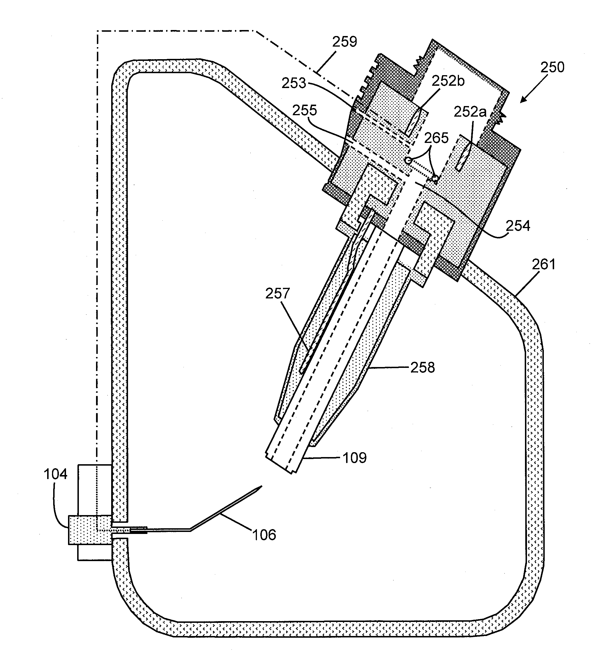
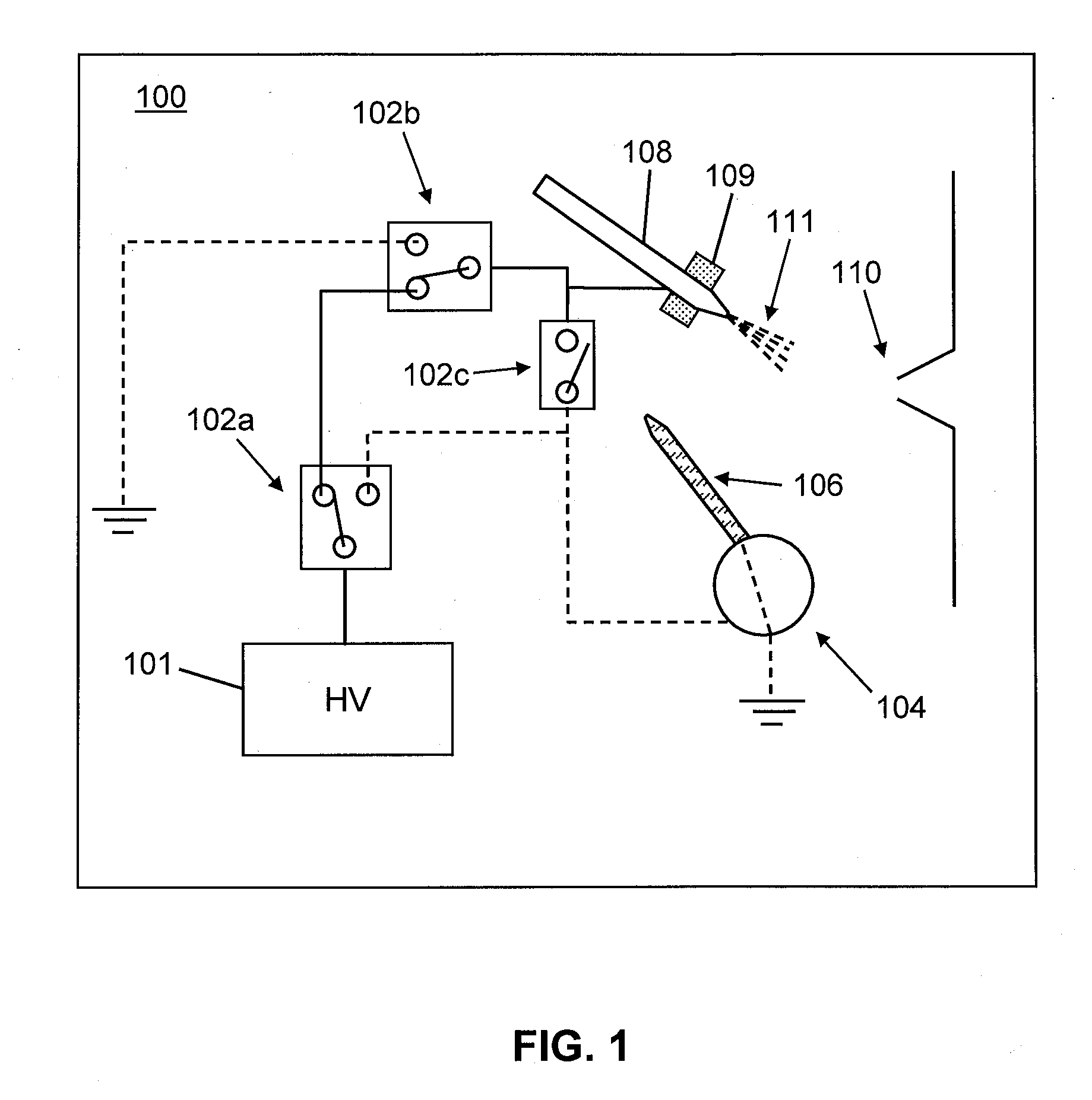
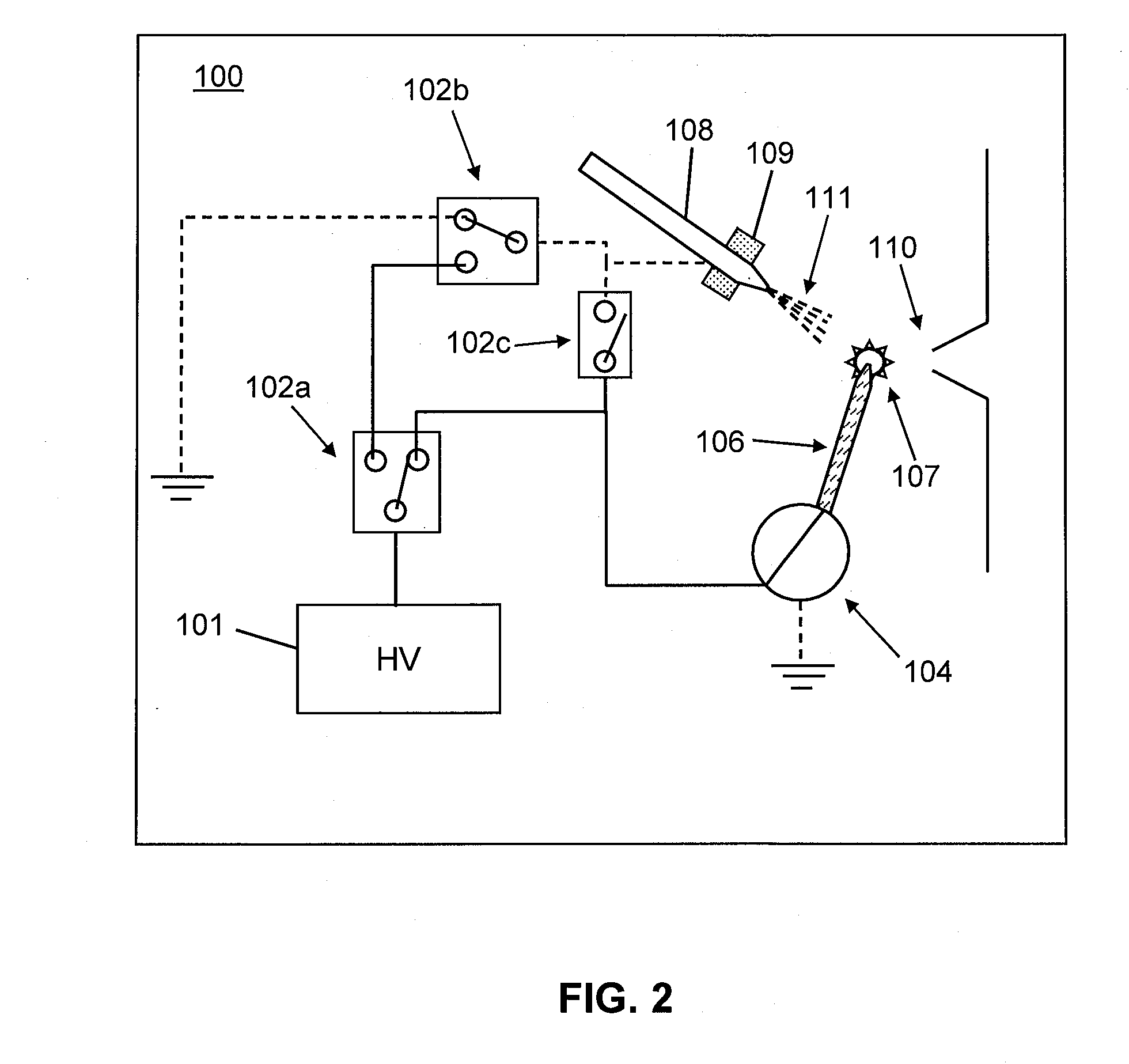
[0006]To address the need for easy and convenient changeover or switching between ESI (or HESI) and APCI ion sources, two related approaches are disclosed herein. Accordingly, in a first aspect of the present teachings, a switchable ion source is provided that can operate in either an HESI-only mode, an APCI-only mode or a “combined mode”. The apparatus facilitates easy and rapid selection between HESI (or ESI) and APCI ionization techniques and, in the combined mode, enables two types of ionization mechanisms to be performed simultaneously to ionize a single sample. Accordingly, a combination HESI / APCI source is described so that either HESI or APCI can be achieved using the same source housing. This is achieved by producing a sprayer having a length intermediate between the lengths of conventional HESI-only and APCI-only sprayers. Furthermore, when HESI mode is in use, the sprayer tip receives an electrical potential and the corona discharge needle is grounded. When APCI mode is in use, the sprayer tip is grounded (or given a small electrical potential) and the corona discharge needle is supplied an electrical potential. Software may be employed to switch between HESI and APCI operational modes between analyses employing different analysis protocols. A single power supply is provided so as to provide operating voltage to either an HESI sprayer, to an APCI needle electrode or to both the sprayer and the APCI needle. The APCI needle may be provided on a moveable or rotatable support that may permit the APCI needle to physically move, under software control, between two positions: a first position—used when Atmospheric Pressure Chemical Ionization is in effect—between the nozzle and an ion inlet aperture of a mass spectrometer and a second position—used when APCI is not in effect—that is removed from the region between the nozzle or sprayer and the ion inlet aperture.
[0007]In a second aspect of the present teachings, modular interchangeable HESI (or ESI) and APCI nozzle assemblies are disclosed, either of which may be mated to a common housing which provides all necessary gas and electrical connections to the mated nozzle assembly. The HESI nozzle assembly includes a single electrical contact that, in operation, mates with an electrically live electrical contact of the housing. Since the single electrical contact of the HESI probe is in electrical communication with the HESI nozzle or sprayer, an operating voltage may thus be applied to the HESI nozzle or sprayer. The APCI nozzle assembly includes a first electrical contact that, in operation, mates with the same electrically live electrical contact of the housing. The APCI nozzle assembly further includes a second electrical contact that, in operation, mates with a second electrical contact of the housing. The first and second electrical contacts of the APCI nozzle assembly are in electrical communication with one another. However, these two electrical contacts may not be in electrical communication with the nozzle or sprayer portion. Thus, in operation, the APCI nozzle assembly may provide a simple electrical bridge between the two electrical contacts of the housing. Since the second housing electrical contact is in electrical communication with an APCI needle within the housing, operating voltage may thus be provided to the APCI needle when the APCI housing assembly is in its operating position.

Problems solved by technology

However, some fundamental differences exist between the two techniques.
However, these two electrical contacts may not be in electrical communication with the nozzle or sprayer portion.

Method used


Image

  • Combined Ion Source for Electrospray and Atmospheric Pressure Chemical Ionization
  • Combined Ion Source for Electrospray and Atmospheric Pressure Chemical Ionization
  • Combined Ion Source for Electrospray and Atmospheric Pressure Chemical Ionization

Examples


Embodiment Construction

[0016]The following description is presented to enable any person skilled in the art to make and use the invention, and is provided in the context of a particular application and its requirements. Various modifications to the described embodiments will be readily apparent to those skilled in the art and the generic principles herein may be applied to other embodiments. Thus, the present invention is not intended to be limited to the embodiments and examples shown but is to be accorded the widest possible scope in accordance with the features and principles shown and described. To appreciate the features of the present invention in greater detail, please refer to FIGS. 1-7 in conjunction with the following discussion.

[0017]The terms “mass spectrometry” or “MS” as used herein refer to methods of filtering, detecting, and measuring ions based on their mass-to-charge ratio, m / z, sometimes given in units “Da / e” (Daltons per elemental charge unit). In general, one or more molecules of int...


PUM


Abstract

A ion source for a mass spectrometer comprises: a capillary having a nozzle for emitting a nebulized fluid sample; an electrode of the capillary; a high voltage power supply; a second electrode disposed within or configurable to be disposed within a path of the nebulized fluid sample; and at least one switch for selecting application of an electrical potential provided by the high voltage power supply to either or both of the capillary electrode or the second electrode, wherein the capillary and capillary electrode are configurable so as to ionize the nebulized fluid sample by electrospray ionization and the second electrode is configurable so as to ionize the nebulized sample by atmospheric pressure chemical ionization.

Description

CROSS-REFERENCE TO RELATED APPLICATIONS[0001]This application claims priority under 35 USC §119(e) to U.S. Provisional Patent Application 61 / 408,034 filed Oct. 29, 2010, entitled “Combined Ion Source for Electrospray and Atmospheric Pressure Chemical Ionization”, the entirety of which is herein incorporated by reference.FIELD OF THE INVENTION[0002]The present invention generally relates to mass spectrometry and, more particularly, to ion sources for generating ions from a sample and delivering the ions to a mass spectrometer.BACKGROUND OF THE INVENTION[0003]Mass spectrometry is a well-established method of analyzing for the presence and concentration (or amount) of a wide variety of chemical constituents with high sensitivity. Since mass spectrometric analysis includes detection or quantification of various ions having varying mass-to-charge ratios, it is necessary to ionize the molecules of chemical constituents of samples of interest. Heated electrospray ionization (HESI) and atmo...

Claims


Application Information

Patent Timeline
IPC IPC(8): H01J49/10H01J27/02
CPCH01J49/165H01J49/167H01J49/145H01J49/107
Inventor HARDMAN, MARKDUNYACH, JEAN-JACQUESATHERTON, R. PAULBELFORD, MICHAEL W.
Owner THERMO FINNIGAN
Learn More