Eureka AIR delivers breakthrough ideas for toughest innovation challenges, trusted by R&D personnel around the world.

Thermally insulating turbine coupling

a turbine and thermal insulation technology, applied in the direction of machines/engines, mechanical equipment, liquid fuel engines, etc., can solve the problems of structural reliability, large propagation rate, and the turbine is not used in the production engine, and achieves precise alignment and concentricity, limit stresses, and easy disassembly/reassembly.

Active Publication Date: 2012-04-19
IMPERIAL INNOVATIONS LTD +1
View PDF24 Cites 9 Cited by
  • Summary
  • Abstract
  • Description
  • Claims
  • Application Information

AI Technical Summary

Benefits of technology

[0020]According to another aspect of the invention, a method of reducing heat transfer in a rotor assembly can be provided. A rotating thermal insulator can be rigidly attached to either a driven member or a driving member. Then the driven member can be coupled to the driving member with a coupling feature. The coupling feature can be configured to allow radial sliding, relative centering, torque transmission, and axial constraint between the driven member and the driving member.
[0021]According to another aspect of the invention, a rotor assembly can be provided that includes at least one driven member and at least one driving member. Additionally, at least one rotating insulator can be provided that is rigidly attached to either the driven member or the driving member. A coupling feature that includes mating geometric surfaces on the driven member and the driving member can be provided, wherein the geometric surfaces can be configured to allow the driven member and the driving member to thermally expand and contract at different rates, maintain relative centering, and prevent relative rotation. Finally, a means to maintain an axial force between the driven member and the driving member can be provided.

Problems solved by technology

However, despite extensive research, ceramic turbines are not yet used in production engines due to several problems.
One major problem with ceramic turbines is structural reliability.
Due to the lower fracture toughness (brittleness) of ceramic materials, small internal flaws or cracks have a greater tendency to grow over time when the material is under stress, eventually leading to failure.
The larger the initial flaw or crack, the greater the propagation rate and the sooner the part will fail.
However, physically small turbine rotors also have their limitations.
Small turbine rotors, particularly those with ceramics, high turbine inlet temperatures, and brazed joints, typically suffer from bearing overheating.
Therefore, at least one of the two main bearings must unavoidably be positioned inches from the hot turbine rotor, which makes bearing cooling a very difficult engineering problem.
The higher the turbine inlet temperature, the more difficult the cooling problem.
Ceramic turbines are only used when a very high turbine inlet temperature is desired, so invariably, bearing cooling is an extraordinarily difficult design challenge in these cases.
However, in small, simple engines, this is approach is undesirable because it makes the engine more complex; and thus, more expensive and more prone to failure.
However, this system tends to lead to additional problems, such as carbon formation, smoke generation in the combustor, and fuel injector coking.
This requirement forces the bearings to be positioned near the combustor, exacerbating the thermal problems.
Because of these constraints, small turbine engine bearings typically operate at steady-state temperatures around 300 degrees Celsius, which greatly reduces their load capacity and increases the wear rate.
Another major problem with ceramic turbines has been the difficulty in joining ceramic turbine rotors to metal shafts.
If the ceramic turbine and metal shaft are bonded together rigidly, this can cause large stresses that can break the ceramic material or yield the metal, causing the joint to fail.
However, cylindrical joints, which are typically the most common type of joint most likely due to its apparent simplicity, cannot maintain concentricity and strength when the two cylindrical parts repeatedly move relative to each other.
Therefore, cylindrical joints that move during operation can quickly fail.
However, the substitution of the ceramic shaft approach is rarely used for various reasons.
This process only works if the filler metal “wets” both materials, which is a constraint that severely limits the range of choices for the filler metal.
Few filler metals are available that have all of these properties.
Therefore, if not done properly, the process can result in joint failure.
However, the problem of keeping the bearings cool still exists, particularly for small engines as explained above.
Therefore, the result is that the cross sectional area for heat conduction is also large.
Since shaft dynamics considerations limit the maximum length of the shaft overall, and in particular the maximum distance between the turbine rotor and the bearing, it is not possible to simply use a long shaft to insulate the bearing from this heat conducted from the turbine.
It is also difficult to squeeze a thermally insulating feature into this very constrained space on the shaft.
A final problem with brazed joints is that they cannot be disassembled.
Therefore, once assembled, the entire rotating assembly can be especially difficult to take back apart.
This can make it very difficult to design a gas turbine engine that can readily be repaired easily and quickly.
In summary, brazed and adhesively bonded joints are permanent, and cannot be easily disassembled.
They can be difficult to design manufacture, and they typically conduct too much heat to the bearings, which is unavoidable due to shaft dynamics considerations.
This problem is particularly severe in small engines; and therefore, the bearings of ceramic turbine engines, particularly small ones, tend to fail often and need frequent replacement.
However, the geometry of the joint should also accommodate thermal strains that inevitably arise due to different thermal expansion coefficients and heating / cooling rates of the mating components.

Method used


Image

  • Thermally insulating turbine coupling
  • Thermally insulating turbine coupling
  • Thermally insulating turbine coupling

Examples


Embodiment Construction

[0032]Referring now to the drawings, in which like numerals represent like elements, aspects of the exemplary embodiments will be described in connection with the drawing set.

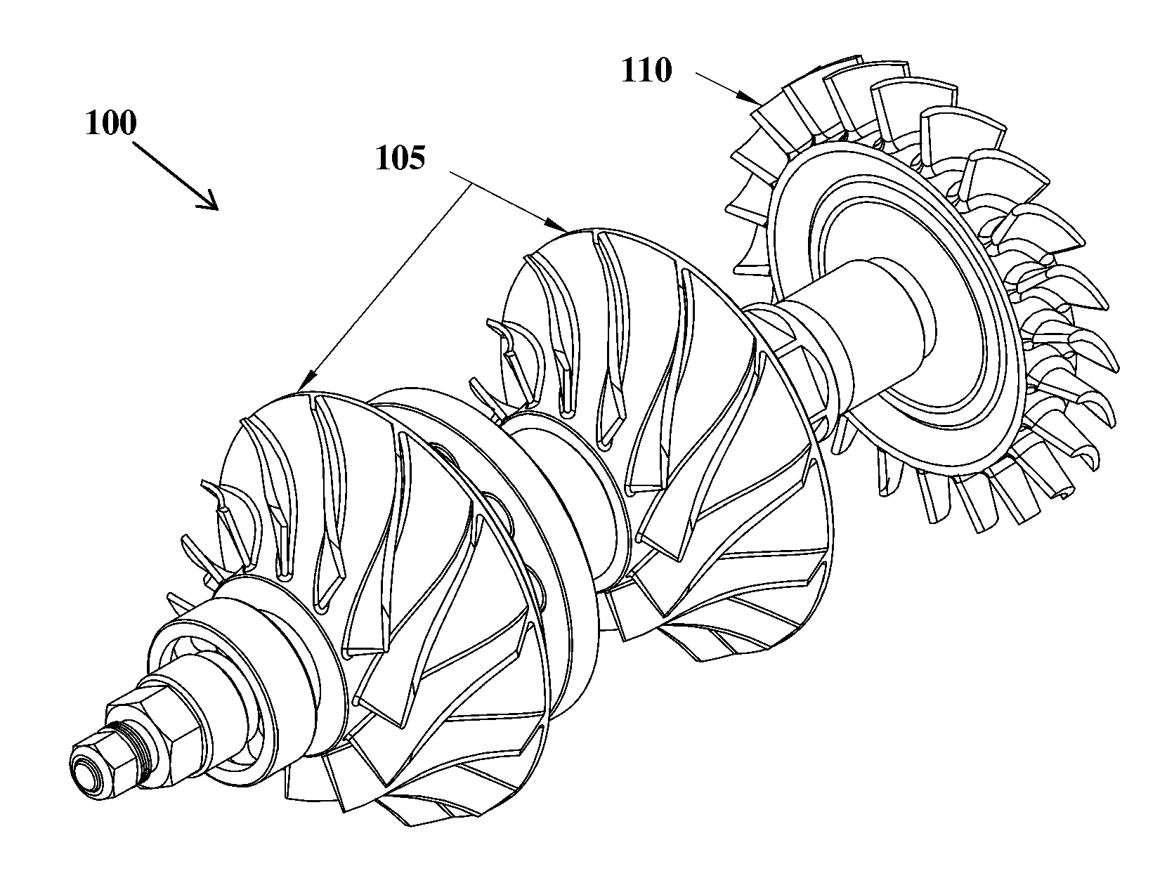
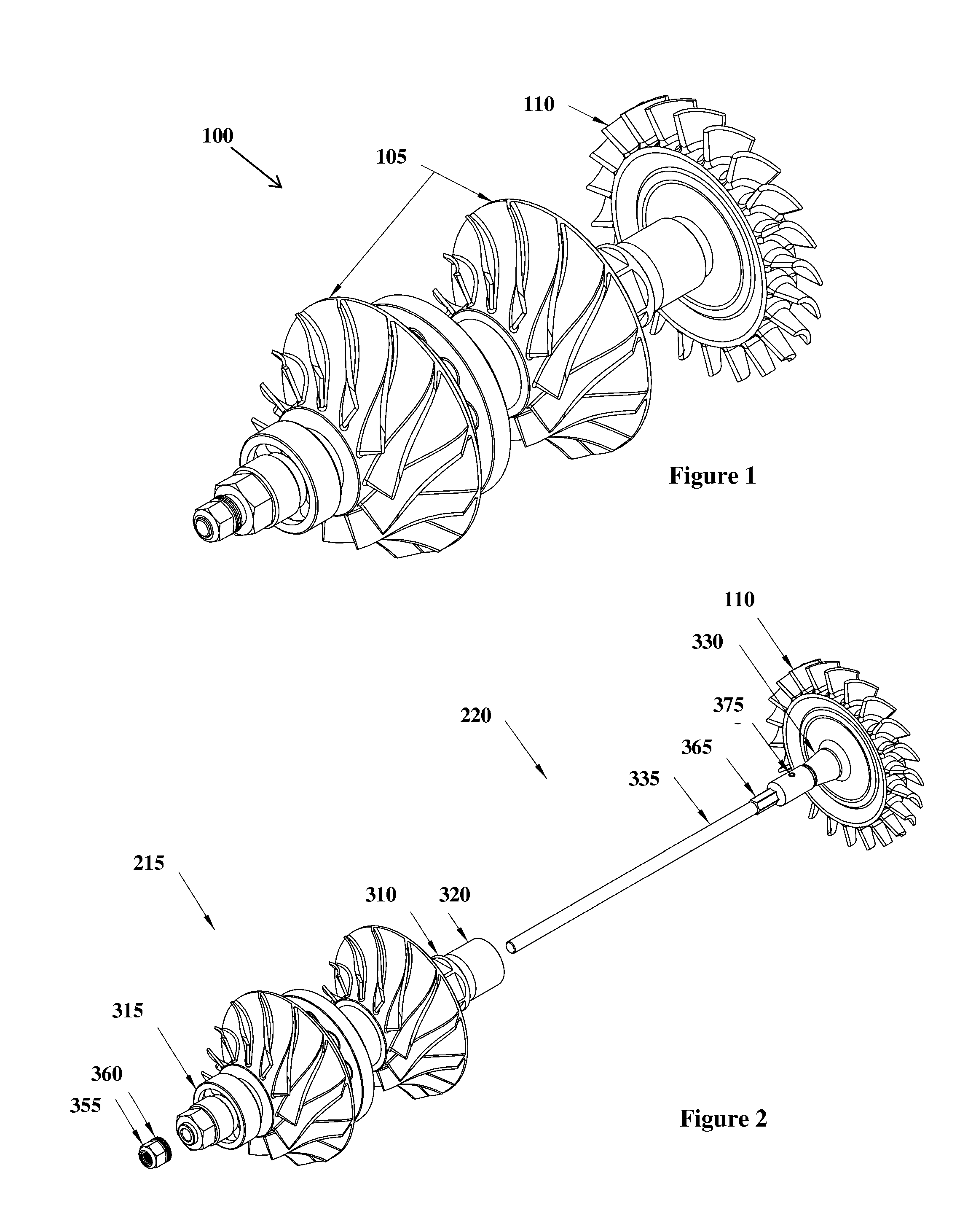
[0033]FIG. 1 is an isometric view of an exemplary rotor assembly 100 for a gas turbine engine, in accordance with an exemplary embodiment of the invention. The rotor assembly 100 includes a two-stage compressor impeller assembly 105 and a single stage axial flow turbine rotor 110. However, one of ordinary skill in the art would understand that a rotor assembly with different types, and different quantities, of components could also be utilized so long as there is at least one high speed, high-temperature rotating component such as a turbine, and at least one high speed rotating component that needs to stay comparatively cool, such as a compressor, generator, gearbox, etc. Furthermore, it is immaterial whether the compressor has a single stage or multiple stages, and whether it is centrifugal, axial, or mixed fl...


PUM


Abstract

A rotor assembly, including at least one driven member, e.g., a compressor rotor, and at least one driving member, e.g., a turbine. At least one rotating thermal insulator rigidly attached to either the driven member or the driving member. A coupling feature that includes mating geometric surfaces on the driven member and the driving member, wherein the geometric surfaces are configured to allow radial sliding, relative centering, torque transmission, and axial constraint between the driven member and the driving member.

Description

CROSS-REFERENCE TO RELATED APPLICATIONS[0001]This application claims priority to U.S. Provisional Patent Application entitled, “Thermally Insulating Turbine Coupling,” filed on Oct. 13, 2010, and assigned U.S. Application No. 61 / 392,820; the entire contents of which are hereby incorporated by reference.FIELD OF THE INVENTION[0002]The invention relates to turbine rotors. More specifically, the invention relates to providing a strong, precise, thermally insulating, thermal stress resistant method for joining a turbine rotor to a metal shaft.BACKGROUND[0003]Ceramic turbines are of interest for high-efficiency gas turbine engines because ceramic materials can tolerate higher temperatures than metals, leading directly to higher fuel efficiency. However, despite extensive research, ceramic turbines are not yet used in production engines due to several problems.[0004]One major problem with ceramic turbines is structural reliability. Due to the lower fracture toughness (brittleness) of cera...

Claims


Application Information

Patent Timeline
Patent Type & Authority Applications(United States)
IPC IPC(8): F04D29/00
CPCF04D29/054F04D25/04F01D5/025F01D5/026F05D2260/231
Inventor VICK, MICHAEL J.PULLEN, KEITH R.
Owner IMPERIAL INNOVATIONS LTD
Why Eureka
Eureka Blog
Learn More