Eureka AIR delivers breakthrough ideas for toughest innovation challenges, trusted by R&D personnel around the world.

Method of Artificial Nueral Network Loadflow computation for electrical power system

a technology of electrical power system and loadflow computation, applied in the direction of biological neural network models, ac networks with different sources at the same frequency, position/direction control, etc., can solve the problems of change in the pattern of power flow in the network, over/under voltage, and small and large disturbances in the healthy operating power network, and achieve the effect of improving the efficiency of the prior art ssdl computation method

Active Publication Date: 2012-03-29
PATEL SURESHCHANDRA B
View PDF8 Cites 66 Cited by
  • Summary
  • Abstract
  • Description
  • Claims
  • Application Information

AI Technical Summary

Benefits of technology

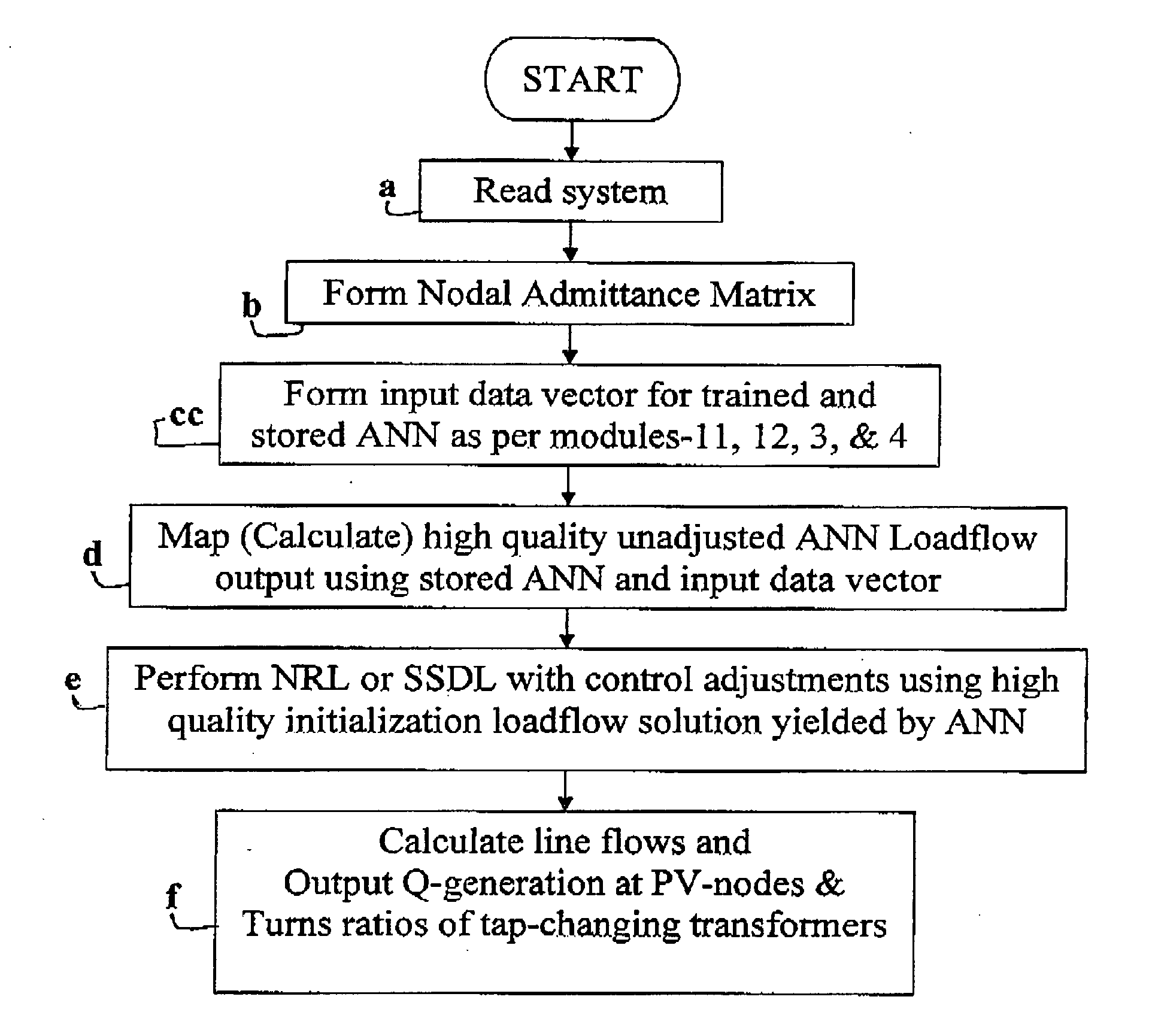
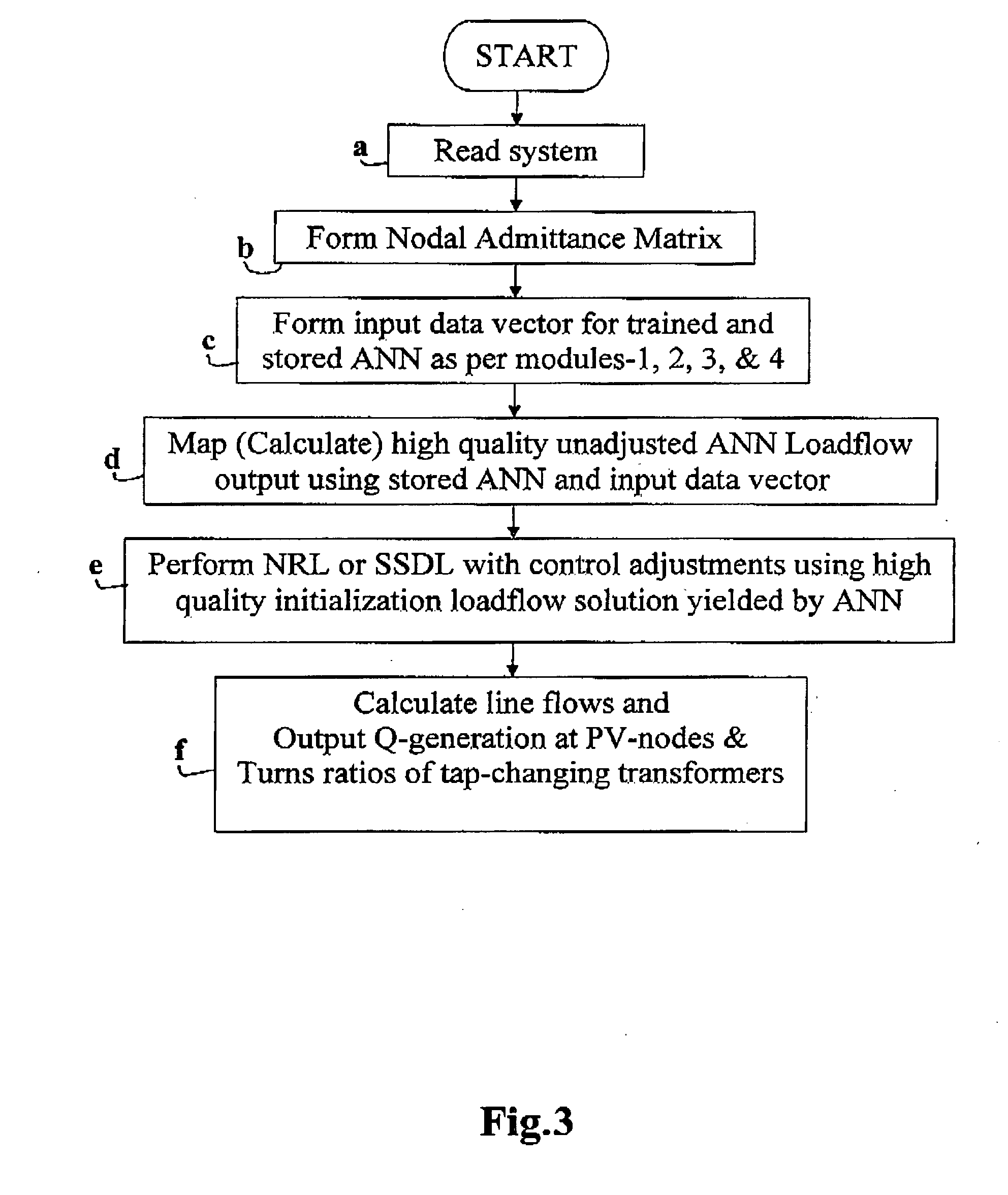
[0045]The inventive system of ANNL computation can be used to solve a model of the Electrical Power System for voltage control. For this purpose real and reactive power assignments or settings at PQ-nodes, real power and voltage magnitude assignments or settings at PV-nodes and transformer turns ratios, open / close status of all circuit breaker, the reactive capability characteristic or curve for each machine, maximum and minimum tap positions limits of tap changing transformers, operating limits of all other network components, and the impedance or admittance of all lines are supplied. ANNL model gives output very fast by performing simple arithmetic operations on inputs corresponding to power system operating condition. The output of ANNL is supplied as high quality initial solution estimate to the conventional SSDL model for completing solution with control adjustments incorporated quickly in two to three iterations. During this solution the quantities, which can vary are the real and reactive power at the reference / slack node, the reactive power set points for each PV-node generator, the transformer transformation ratios, and voltages on all PQ-nodes nodes, all being held within the specified ranges. When the iterative process converges to a solution, indications of reactive power generation at PV-nodes and transformer turns-ratios or tap-settings are provided. Based on the known reactive power capability characteristics of each PV-node generator, the determined reactive power values are used to adjust the excitation current to each generator to establish the reactive power set-points. The transformer taps are set in accordance with the turns ratio indication provided by the SSDL computation.

Problems solved by technology

In other words healthy operating power network is constantly subjected to small and large disturbances.
Such a disturbance would cause a change in the pattern of power flows in the network, which can cause over loading of one or more of the other components and / or over / under voltage at one or more nodes in the rest of the network.
This in turn can isolate one or more other components out of service by virtue of the operation of associated protection, which disturbance can trigger chain reaction disintegrating the power network.
Failure to yield converged loadflow solution creates blind spot as to what exactly could be happening in the network leading to potentially damaging operational and control decisions / actions in capital-intensive power utilities.
If the equations do not describe / represent the power network and its operation accurately the model is inaccurate, and the iterative loadflow computation method could be slow and unreliable in yielding converged loadflow computation.
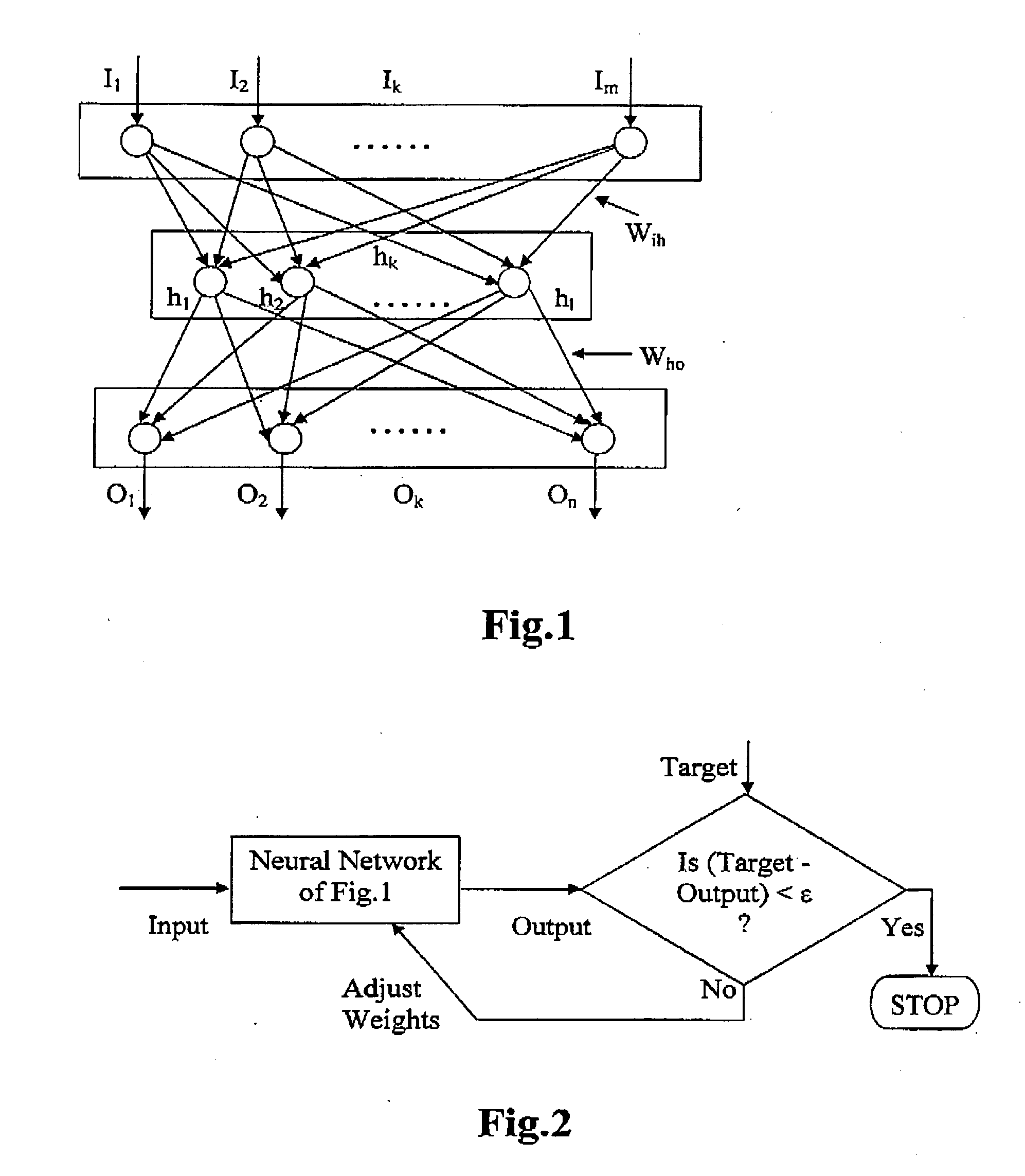
Clearly, the proper choice of all these parameters is very difficult and involves too many trials as well as uncertainties leading to several thousands of iterations for the convergence of training and testing or validating process.

Method used


Image

  • Method of Artificial Nueral Network Loadflow computation for electrical power system
  • Method of Artificial Nueral Network Loadflow computation for electrical power system
  • Method of Artificial Nueral Network Loadflow computation for electrical power system

Examples


Embodiment Construction

[0057]A loadflow computation is involved as a step in power flow control and / or voltage control in accordance with FIG. 7 or FIG. 8. A preferred embodiment of the present invention is described with reference to FIG. 6 as directed to achieving voltage control.

[0058]FIG. 9 is a simplified one-line diagram of an exemplary utility power network to which the present invention may be applied. The fundamentals of one-line diagrams are described in section 6.11 of the text ELEMENTS OF POWER SYSTEM ANALYSIS, forth edition, by William D. Stevenson, Jr., McGrow-Hill Company, 1982. In FIG. 9, each thick vertical, line is a network node. The nodes are interconnected in a desired manner by transmission lines and transformers each having its impedance, which appears in the loadflow models. Two transformers in FIG. 6 are equipped with tap changers to control their turns ratios in order to control terminal voltage of node-1 and node-2 where large loads are connected.

[0059]Node-6 is a reference node...


PUM


Abstract

Neural Network Loadflow (NNL) computation method is invented involving input vector composed of net nodal injection of real and reactive powers and diagonal elements of conductance and susceptance matrices multiplied by the squared voltage magnitude components of the flat-start normally used as initial solution estimate guess for loadflow solution by conventional NRL or SSDL methods. Training, and testing / validating input-output data sets are generated by applying uniform and non-uniform scaling factors applied to base case loads at PQ-nodes, resistance and reactance of transmission line branches. These scale factors are increased until loadflow solution by conventional methods such as Newton-Raphson Loadflow and Super Super Decoupled Loadflow methods diverge. Divergence of loadflow methods are due to node voltage, node angle, and numerical instabilities. Voltage magnitude and phase angle values in the solution before divergence are respective stability limits and voltage magnitude and phase angle values in loadflow solution provide direct measure to the respective stability margins. Also Suresh's diakoptiks based feature selection technique is presented for ANNs calculating one node variable with one neuron each in their output layers.

Description

TECHNICAL FIELD[0001]The present invention relates to method of Artificial Neural Network Loadflow (ANNL) computation in power flow control and voltage control in an electrical power system.BACKGROUND OF THE INVENTION[0002]The present invention relates to power-flow / voltage control in utility / industrial power networks of the types including many power plants / generators interconnected through transmission / distribution lines to other loads and motors. Each of these components of the power network is protected against unhealthy or alternatively faulty, over / under voltage, and / or over loaded damaging operating conditions. Such a protection is automatic and operates without the consent of power network operator, and takes an unhealthy component out of service by disconnecting it from the network. The time domain of operation of the protection is of the order of milliseconds.[0003]The purpose of a utility / industrial power network is to meet the electricity demands of its various consumers...

Claims


Application Information

Patent Timeline
Patent Type & Authority Applications(United States)
IPC IPC(8): G06F19/00
CPCG06N3/08H02J2003/007H02J3/06H02J2203/20
Inventor PATEL, SURESHCHANDRA B.
Owner PATEL SURESHCHANDRA B
Why Eureka
Eureka Blog
Learn More