Eureka AIR delivers breakthrough ideas for toughest innovation challenges, trusted by R&D personnel around the world.

Video encoding device, video decoding device, video encoding method, and video decoding method

Inactive Publication Date: 2012-03-29
MITSUBISHI ELECTRIC CORP
View PDF3 Cites 67 Cited by
  • Summary
  • Abstract
  • Description
  • Claims
  • Application Information

AI Technical Summary

Benefits of technology

[0013]As mentioned above, in the conventional system disclosed in nonpatent reference 1, the size of each macro block is enlarged to increase the unit to which a motion vector is allocated and reduce the code amount of the parameters required for prediction, and a correlation between pixels of the signal is removed to improve the compression efficiency of the prediction error signal. On the other hand, a problem with the conventional system is that because an application of a large DCT block size is accompanied by an increase in the effective number of digits required to express the transform coefficients, the number of bits required to express the coefficients is increased as a result.
[0014]The present invention is made in order to solve the above-mentioned problems, and it is therefore an object of the present invention to provide a video encoding device which implements a video encoding method having good implementation load balance, of removing a signal correlation more effectively according to the statistical and local properties of a video signal which is a target to be encoded and performing efficient information compression, thereby improving the optimality for encoding of an ultra-high-definition video signal, and a method of implementing the video encoding device, and a video decoding device and a method of implementing the video decoding device.
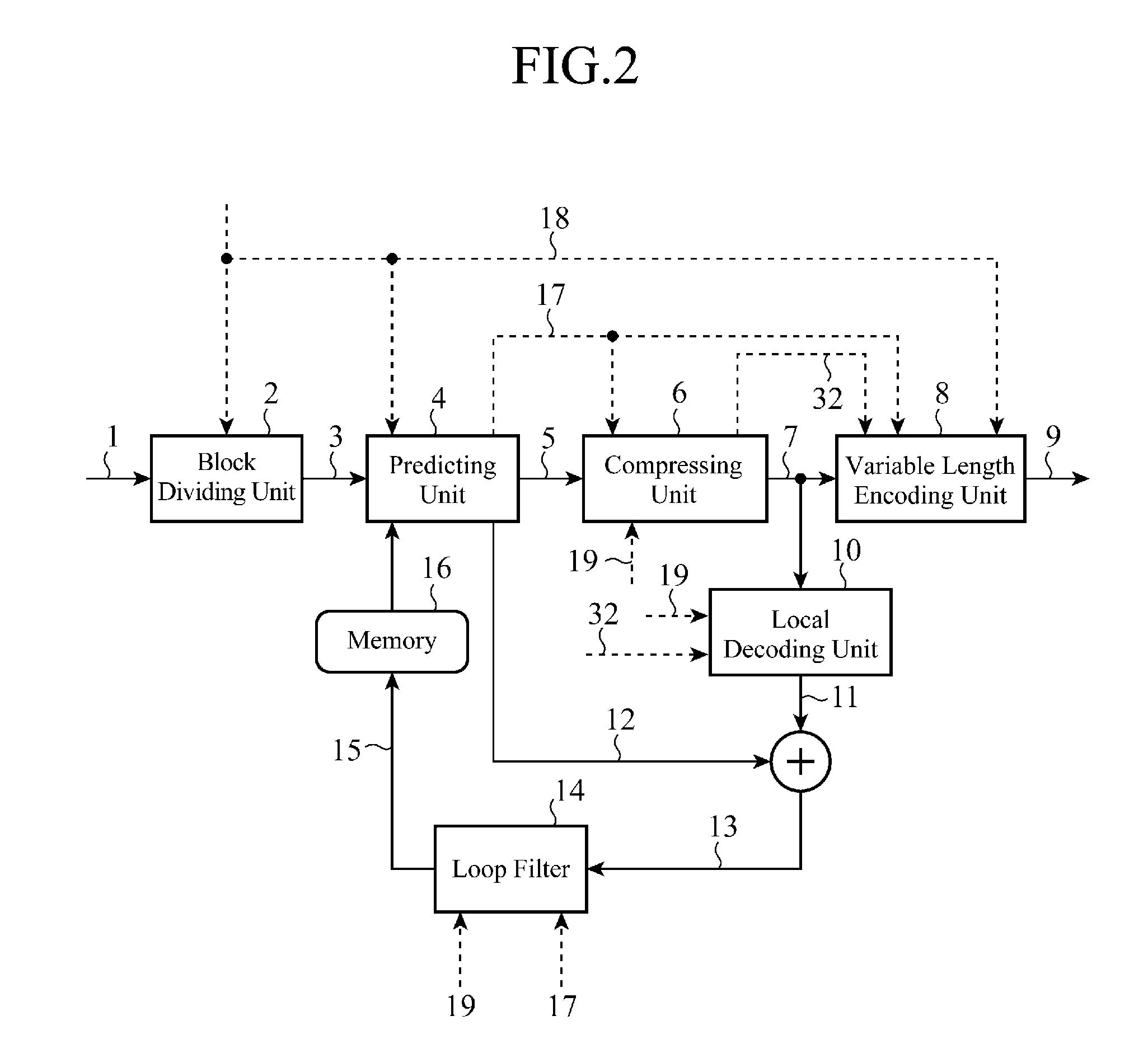
[0019]According to the present invention, the prediction error signal is downsampled, and is then transformed and quantized to create the quantized and transformed coefficients while the quantized and transformed coefficients are upsampled, and are then inverse-quantized and inverse-transformed to create the decoded prediction error signal. Therefore, the video encoding method can be implemented to have good implementation load balance, and remove a signal correlation more effectively according to the statistical and local properties of a video signal which is a target to be encoded and perform efficient information compression. As a result, the video encoding device, the video encoding method, the video decoding device, and the video decoding method can improve their optimality for the encoding of an ultra-high-definition video signal having the 4:4:4 format at a low cost.

Problems solved by technology

On the other hand, a problem with the conventional system is that because an application of a large DCT block size is accompanied by an increase in the effective number of digits required to express the transform coefficients, the number of bits required to express the coefficients is increased as a result.

Method used


Image

  • Video encoding device, video decoding device, video encoding method, and video decoding method
  • Video encoding device, video decoding device, video encoding method, and video decoding method
  • Video encoding device, video decoding device, video encoding method, and video decoding method

Examples


embodiment 1

[0033]Hereafter, the preferred embodiments of the present invention will be explained in detail with reference to the drawings.

[0034]In this embodiment, a video encoding device which performs compression of a digital video signal having a 4:4:4 format inputted thereto and which is adapted for the state of a signal of each color component to perform a motion compensation prediction process, and a video decoding device which performs decompression of a digital video signal having a 4:4:4 format and which is adapted for the state of a signal of each color component to perform a motion compensation prediction process will be described.

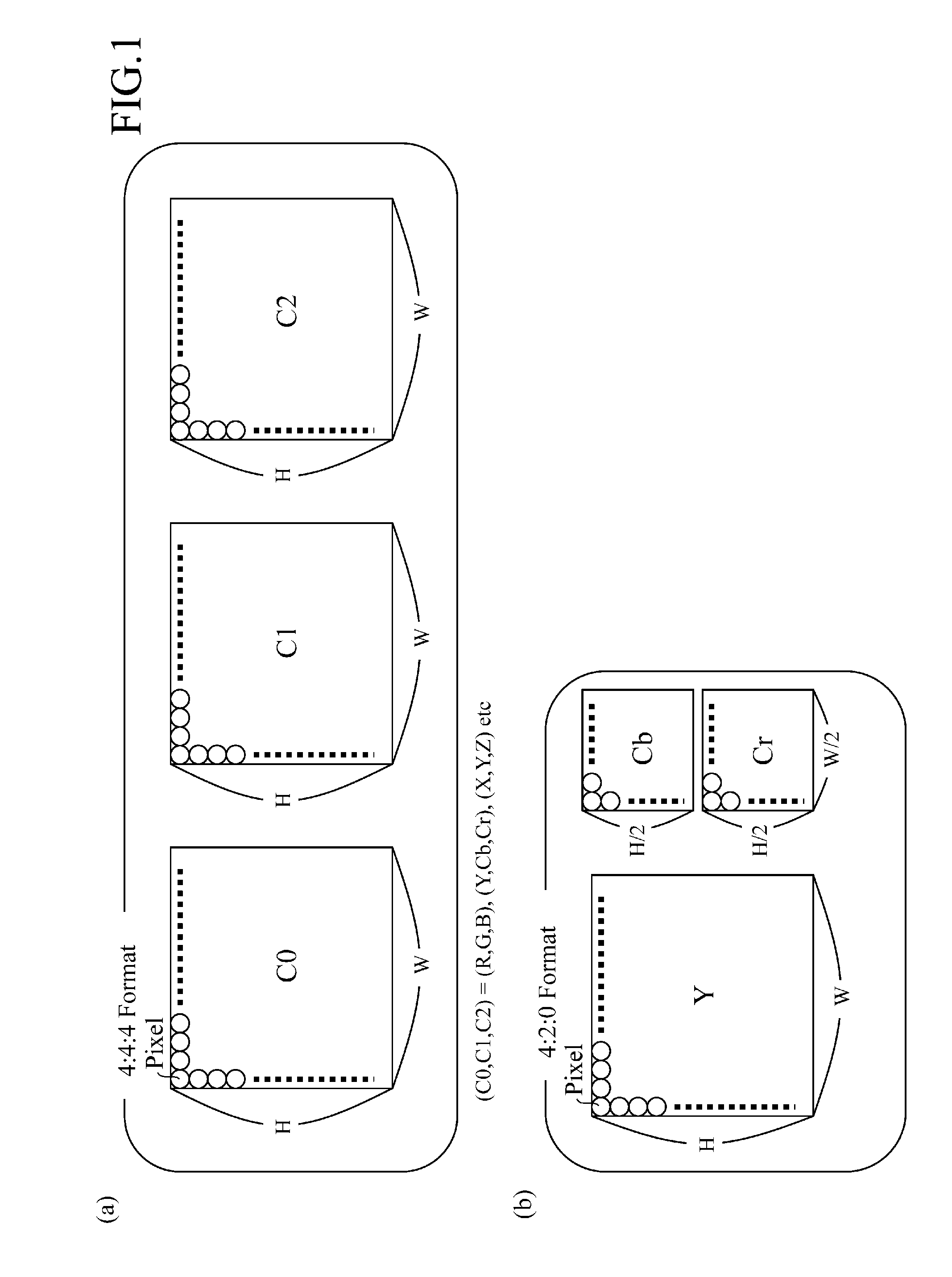
[0035]FIG. 1 shows the 4:4:4 format which the video encoding device and the video decoding device in accordance with Embodiment 1 use as the format of an input. The 4:4:4 format denotes a format in which, as shown in FIG. 1(a), the number of pixels of three signal components C0, C1, and C2 which construct a color moving image are the same as one another. T...


PUM


Abstract

A compressing unit 6 of a video encoding device selects whether or not to transform and quantize a prediction error signal 5 after a downsampling processing unit 36 performs a reduction transformation on the prediction error signal 5 by using a transforming process determining unit 31, and then creates quantization coefficient data 7a or 7b. When the compressing unit creates the quantization coefficient data 7b, a local decoding unit located behind the compressing unit inverse-quantizes and inverse-transforms the quantization coefficient data 7b, and, after that, an upsampling processing unit performs an enlargement transformation on the quantization coefficient data to create a decoded prediction error signal.

Description

FIELD OF THE INVENTION[0001]The present invention relates to a video encoding device, a video decoding device, a video encoding method, and a video decoding method which are used for a video compression encoding technique, a compressed video data transmission technique, etc.BACKGROUND OF THE INVENTION[0002]Conventionally, in international standard video encoding methods, such as MPEG and ITU-T H .26x, each input video frame is subjected to a compression process with the video frame being divided into macro blocks each of which consists of 16×16 pixel blocks.[0003]On the other hand, in recent years, a technique of compression-encoding a high-definition high-quality video having a video format, such as a 4K×2K-pixel video format having an image resolution which is four times as high as that of HDTV (High Definition TeleVision, 1920×1080 pixels), an 8K×4K-pixel video format having an image resolution which is further increased to four times as high as that of the 4K×2K-pixel video form...

Claims


Application Information

Patent Timeline
IPC IPC(8): H04N7/32
CPCH04N19/105H04N19/176H04N19/147H04N19/46H04N19/117H04N19/59H04N19/186H04N19/537H04N19/543H04N19/567H04N19/127
Inventor SUGIMOTO, KAZUOSEKIGUCHI, SHUNICHIITANI, YUSUKEMINEZAWA, AKIRAYAMAGISHI, SHUICHI
Owner MITSUBISHI ELECTRIC CORP
Why Eureka
Eureka Blog
Learn More