Electronic Control Device
a control device and electronic technology, applied in the direction of electrical equipment, printed circuits, coupling device connections, etc., can solve the problem of increasing the size of the control uni
- Summary
- Abstract
- Description
- Claims
- Application Information
AI Technical Summary
Benefits of technology
Problems solved by technology
Method used
Image
Examples
first embodiment
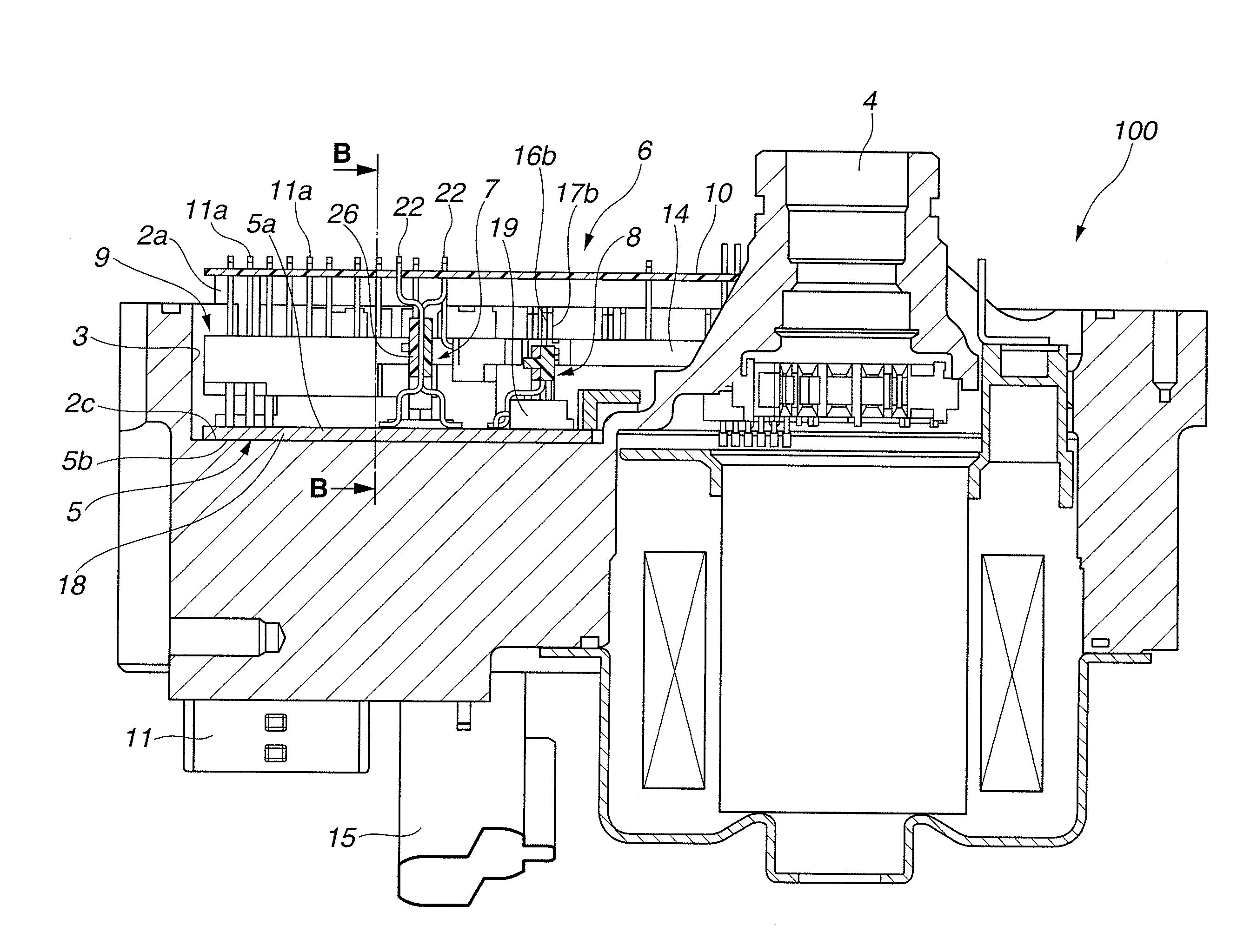
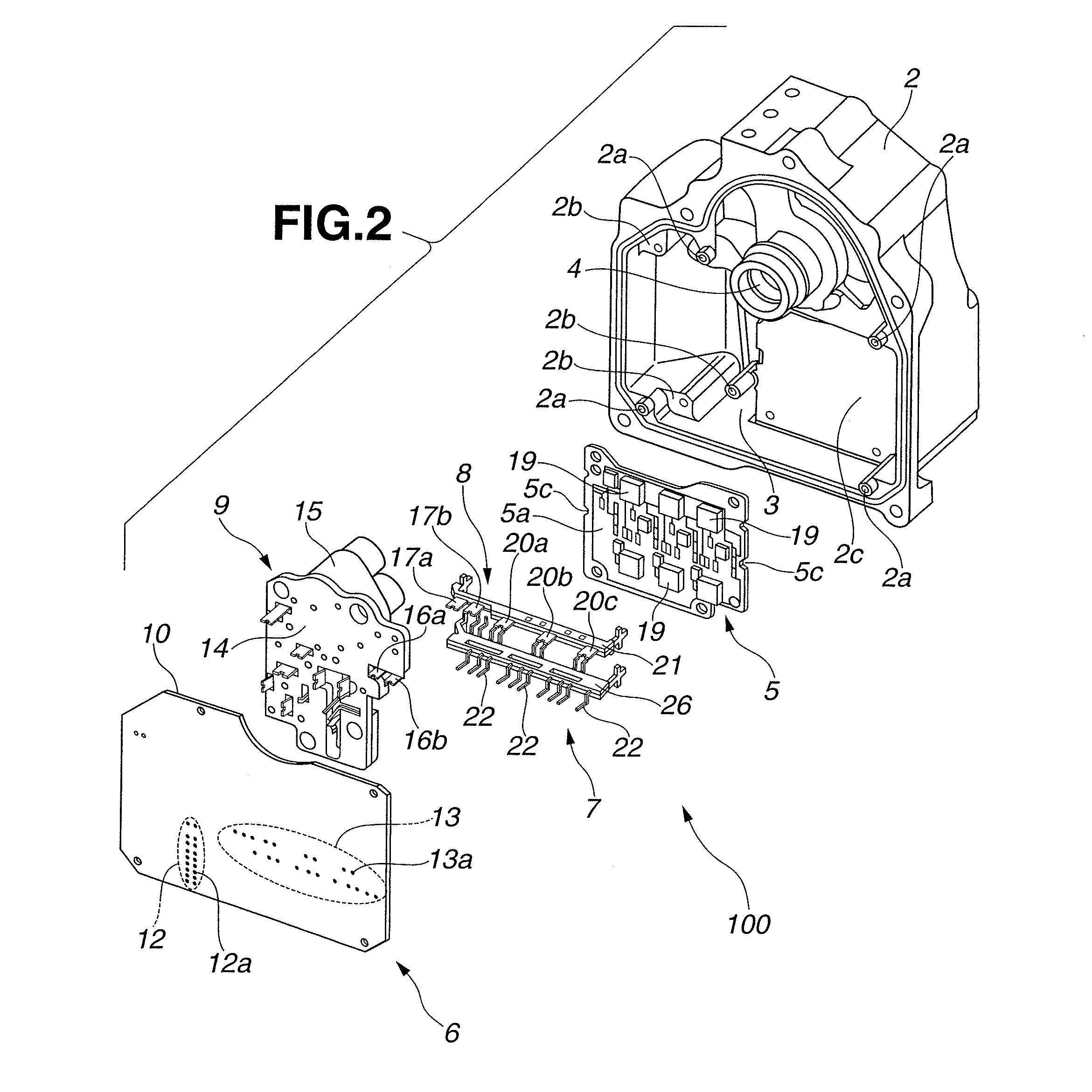
[0046]Therefore, in the first embodiment according to the present invention, as seen from FIGS. 4 and 8, in terminal-pin dense regions A1-A4 of signal-system lead frame 7 in which the intervals between signal-system terminal pins 22 adjacent to each other are minimum, the adjacent signal-system terminal pins 22 are arranged to have such a mounting attitude that the adjacent signal-system terminal pins 22 are angularly displaced from each other by 180 degrees in a direction of rotation about intermediate connecting portion 25a (see FIG. 7). That is, in the respective terminal-pin dense regions A1-A4, signal-system terminal pin 22 having connecting portions 23, 24 located on one side of intermediate connecting portion 25a in the direction perpendicular to the alignment direction of signal-system terminal pins 22, and signal-system terminal pin 22 having connecting portions 23, 24 located on the other side of intermediate connecting portion 25a in the direction perpendicular to the ali...
second embodiment
[0058]FIG. 9 is a perspective view of an electronic control device according to the present invention, showing a power module to which a signal-system lead frame is mounted. In FIG. 9, for the sake of simple illustration, power-system lead frame 8, respective switching elements 9, etc. are omitted.
[0059]As shown in FIG. 9, in electronic control device 200 according to the second embodiment, signal-system terminal pin 22 having connecting portions 23, 24 located on one side of intermediate connecting portion 25a in the direction perpendicular to the alignment direction of signal-system terminal pins 22 (i.e., the alignment direction of intermediate connecting portion 25a), and signal-system terminal pin 22 having connecting portions 23, 24 located on the other side of intermediate connecting portion 25a in the direction perpendicular to the alignment direction of signal-system terminal pins 22 are alternately arranged in the alignment direction of signal-system terminal pins 22 over ...
third embodiment
[0061]As explained above, in view of the fabricating method, it is necessary to ensure certain intervals between respective pads 32 of power module 5 and certain intervals between respective through-holes 13a in the alignment direction of signal-system terminal pins 22. It is generally known that a minimum interval to be provided between the adjacent lands formed around respective pads 32 or through-holes 13a becomes larger in proportion to a thickness of a metal foil forming a conductive pattern thereon. The minimum interval between through-holes 13a of control module 6 which has a conductive pattern formed using a metal foil thinner than that for power module 5 can be reduced as compared to the minimum interval between adjacent pads 32 of power module 5. Therefore, there is provided an electronic control device as shown in FIG. 10 and FIG. 11, in which the control module side connecting portion of the respective signal-system terminal pins and the intermediate connecting portion ...
PUM
 Abstract
Description
Claims
Application Information
 - R&D
- Intellectual Property
- Life Sciences
- Materials
- Tech Scout
- Unparalleled Data Quality
- Higher Quality Content
- 60% Fewer Hallucinations
Browse by: Latest US Patents, China's latest patents, Technical Efficacy Thesaurus, Application Domain, Technology Topic, Popular Technical Reports.
© 2025 PatSnap. All rights reserved.Legal|Privacy policy|Modern Slavery Act Transparency Statement|Sitemap|About US| Contact US: help@patsnap.com


