
Terminal block connection structure in rotary electric machine

Active Publication Date: 2017-04-13
TOYOTA JIDOSHA KK
View PDF1 Cites 3 Cited by
  • Summary
  • Abstract
  • Description
  • Claims
  • Application Information

AI Technical Summary

Benefits of technology

The present patent improves the vibration resistance of a power line in a terminal block connection structure for a rotary electric machine. This is achieved by using bus bars with L-shaped portions that are connected to the power lines through a resin member. The connector is fitted to the resin member to prevent movement, and the plurality of bus bars is fixed to the terminal block. This structure restrains vQuantitative analysis: The patent describes a way to make a connection between power lines and a terminal block for a rotary electric machine. The connection is made through bus bars that have L-shaped portions. The bus bars are connected to the terminal block, and a connector is used to join them. This design helps to prevent vibrations during use and improves the strength of the power line. The goal is to make the connection more resistant to vibrations while keeping it simple and cost-effective.

Problems solved by technology

In a configuration in which a plurality of power lines is integrated by a connector, like the configuration described in JP 2014-128095 A, when large vibrations are added at the time of the use of a rotary electric machine, a vibration of the connector may cause a large vibration of the power lines.

Method used


Image

  • Terminal block connection structure in rotary electric machine
  • Terminal block connection structure in rotary electric machine
  • Terminal block connection structure in rotary electric machine

Examples


Embodiment Construction

[0038]Exemplary embodiments of the present disclosure, with reference to the drawings, are described in detail. A shape, a material, and a number to be described below are exemplifications for descriptions, and they can be changed appropriately according to a specification of a structure for connecting a power line to a terminal block of a rotary electric machine. In the following description, similar elements in all drawings have the same reference sign. Note that a stator constitutes a rotary electric machine in combination with a rotor fixed to a rotating shaft. The rotary electric machine is used as a motor or a generator, or a motor generator having functions of both the motor and the generator.

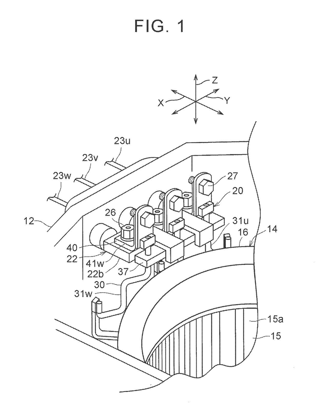
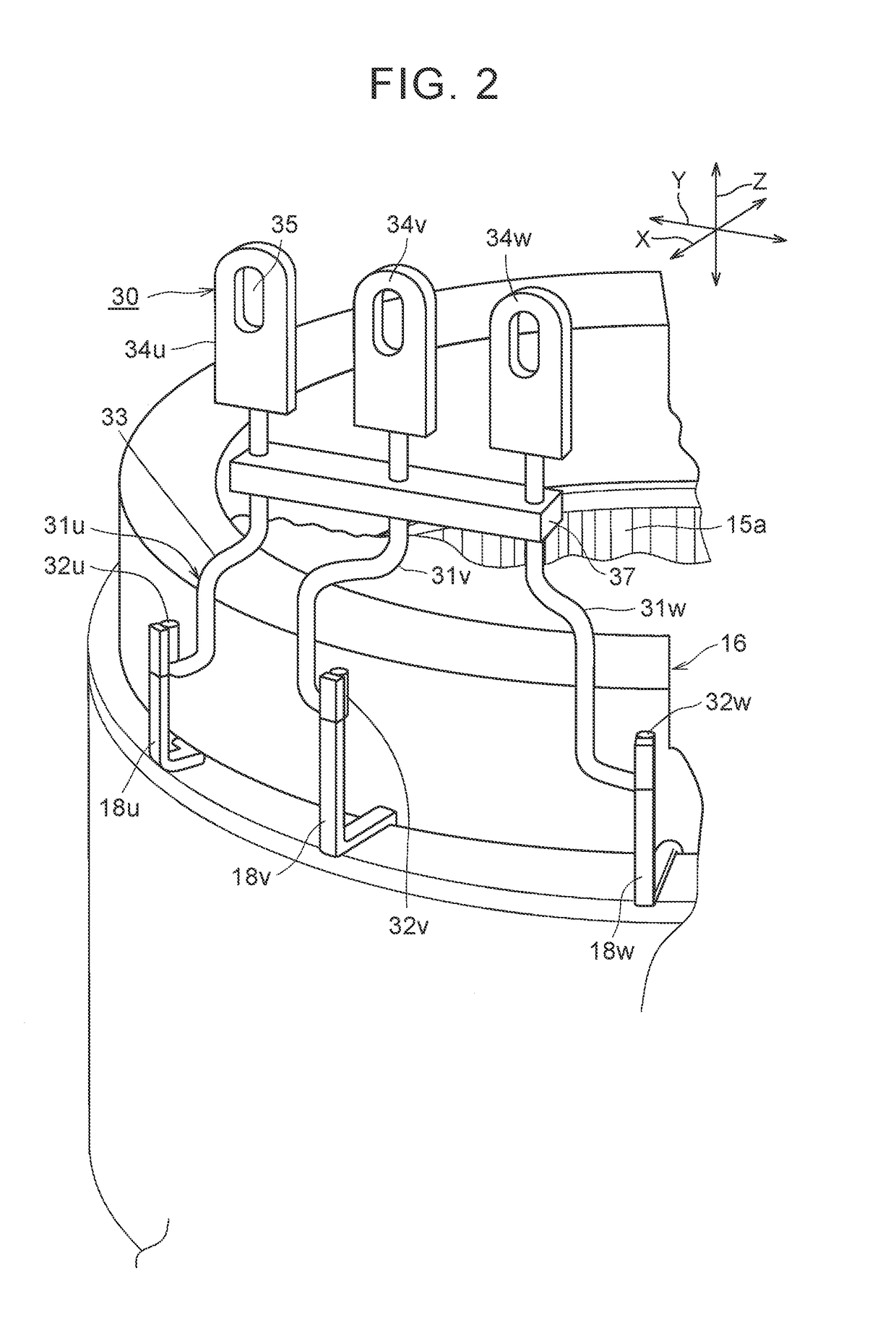
[0039]FIG. 1 is a perspective view of a stator fixing structure 10 including a connection structure 20 when viewed inward from an outside of a case 12. The connection structure 20 is a structure for connecting the power lines 31u, 31v, 31w to the terminal block of the rotary electric mac...


PUM


Abstract

A terminal block connection structure includes: a connector connected to intermediate parts of a plurality of power lines; a bus bar unit including a plurality of bus bars and at least one resin member; a terminal block being configured such that the distal ends of the plurality of power lines are connected to each other via the bus bar unit. The plurality of bus bars each includes a first plate portion fixed to the terminal block and a second plate portion bent from one end of the first plate portion. The connector is fitted to the resin member which is configured to prevent a movement of the connector in at least one direction out of moving directions of the connector.

Description

CROSS-REFERENCE TO RELATED APPLICATIONS[0001]The disclosure of Japanese Patent Application No. 2015-199522 filed on Oct. 7, 2015 including the specification, drawings and abstract is incorporated herein by reference in its entirety.BACKGROUND1. Technical Field[0002]The present disclosure relates to improvement in a vibration resistance of a terminal block connection structure for a rotary electric machine stator including a plurality of power lines connected to a stator coil of a rotary electric machine, a connector for integrating the plurality of power lines, and a terminal block to which distal ends of the plurality of power lines are connected.2. Description of Related Art[0003]A rotary electric machine, which is a motor or a generator, includes a stator and a rotor. A plurality of power lines corresponding to a plurality of phases is connected to a stator coil having the plurality of phases in the stator. Terminals of respective power lines are connected to a terminal block fix...

Claims


Application Information

Patent Timeline
IPC IPC(8): H01R9/24H02K5/22
CPCH02K5/225H01R9/2416H02K3/50H02K5/22H02K2203/03H02K3/522H02K2203/09
Inventor KURONO, YOUSUKEMAKIDO, YASUHIROSASAKI, RYOSUKE
Owner TOYOTA JIDOSHA KK
Learn More