
Power cable breaking detection method of motor

a detection method and technology for power cables, applied in the direction of electric devices, battery/fuel cell control arrangements, instruments, etc., can solve the problems of excessive pulsation torque, cable breaking detection methods may not detect power cables breaking in driving conditions, and the whole system may not function properly, etc., to achieve an effective plan

Inactive Publication Date: 2012-03-22
HYUNDAI MOTOR CO LTD +1
View PDF2 Cites 14 Cited by
  • Summary
  • Abstract
  • Description
  • Claims
  • Application Information

AI Technical Summary

Benefits of technology

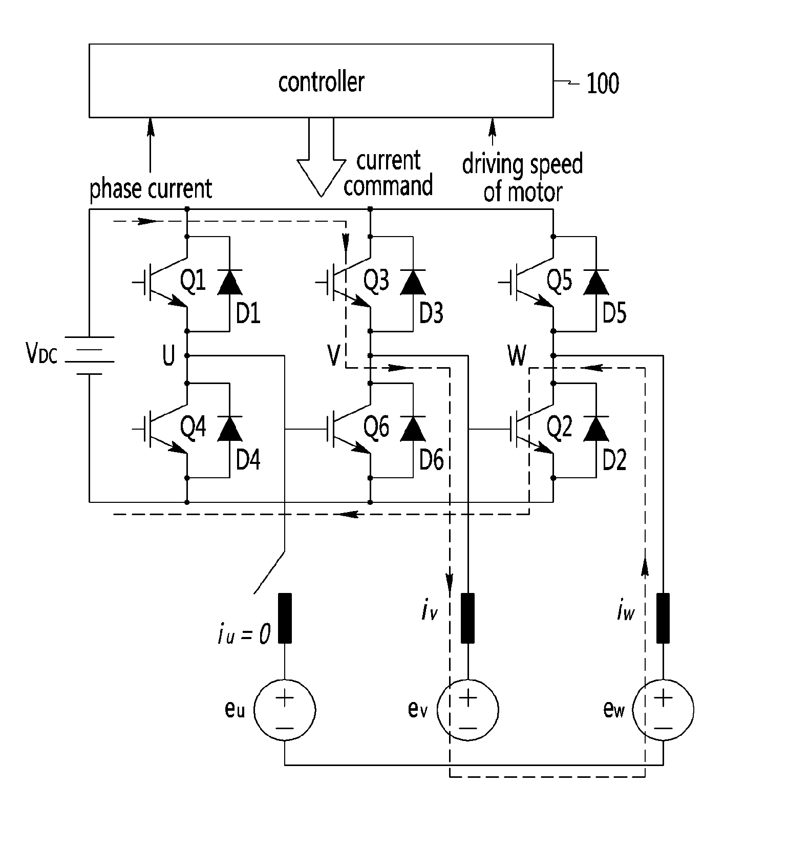
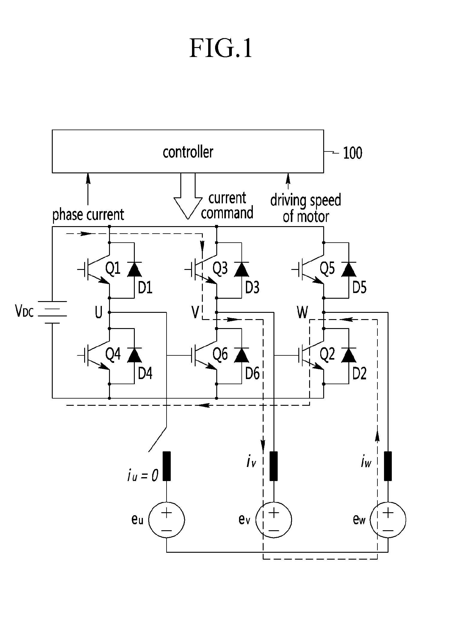
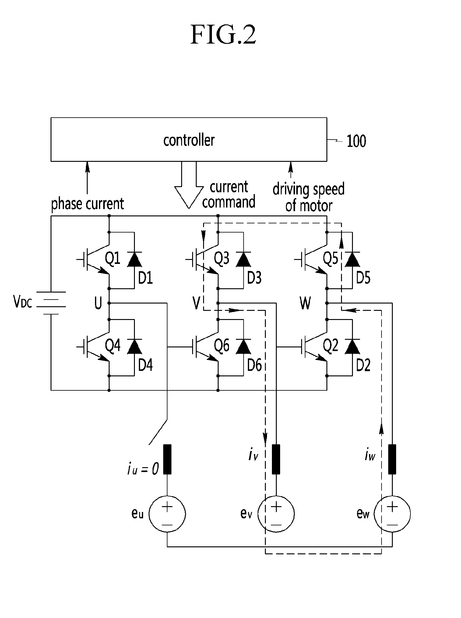
[0014]According to one aspect of the present invention, a power cable breaking detection method is provided for an electric vehicle, a hybrid vehicle, a fuel cell vehicle and the like which may detect a power cable breaking so as to enhance durability and reliability.
[0018]The power cable breaking detection method according to an exemplary embodiment of the present invention may detect a power cable breaking so as to prevent catastrophic damage in early stages.

Problems solved by technology

If a power cable connecting an inverter and a motor is broken or in short circuit, the motor does not operate sufficiently and also, high voltage and high current may be supplied to the inverter, and thus the entire system may not function properly.
Also, a disconnection / short circuit in the power cable may induce an excessive pulsation torque so as to break elements mechanically connected to the motor.
However, a conventional power cable breaking detection method may not detect power cable breaking in driving conditions.
In another conventional power cable breaking detection method, since one phase of current flowing through a broken cable is zero regardless of switching of an inverter, the other 2 current phases may have considerable errors comparing a current command, so errors are detected in order to detect power cable breaking.
However, by using the conventional current control error method, such a method may display a malfunction of current control of an inverter or over current malfunction, and may not detect which phase is malfunctioning, so that it may not be possible to appropriately diagnose and address the malfunction.

Method used


Image

  • Power cable breaking detection method of motor
  • Power cable breaking detection method of motor
  • Power cable breaking detection method of motor

Examples


Embodiment Construction

[0023]Hereinafter, referring to the drawings, exemplary embodiments of the present invention will be described in detail.

[0024]As those skilled in the art would realize, the described embodiments may be modified in various different ways, all without departing from the spirit or scope of the present invention. Description of components that are not necessary for explaining the present invention will be omitted, and the same constituent elements are denoted by the same reference numerals in this specification.

[0025]It is understood that the term “vehicle” or “vehicular” or other similar term as used herein is inclusive of motor vehicles in general such as passenger automobiles including sports utility vehicles (SUV), buses, trucks, various commercial vehicles, watercraft including a variety of boats and ships, aircraft, and the like, and includes hybrid vehicles, electric vehicles, plug-in hybrid electric vehicles, hydrogen-powered vehicles and other alternative fuel vehicles (e.g. f...


PUM


Abstract

A power cable breaking detection method for a vehicle includes detecting currents of respective phases supplied to a three-phase motor from an inverter through at least a power cable, and a driving speed of the motor, determining whether the respective currents and the driving speed of the motor satisfy power cable breaking detection conditions, determining whether various conditions are satisfied with respect to a cable breaking sensing reference value of a current command performing cable breaking timer counting when the conditions are satisfied, and determining whether a predetermined period has elapsed such that a cable is considered broken when the predetermined period has elapsed.

Description

CROSS-REFERENCE TO RELATED APPLICATION[0001]This application claims priority to and the benefit of Korean Patent Application No. 10-2010-0092053 filed in the Korean Intellectual Property Office on Sep. 17, 2010, the entire contents of which are incorporated herein by reference.BACKGROUND OF THE INVENTION[0002](a) Field of the Invention[0003]The present invention relates to a power cable breaking detection method for an electric vehicle, a hybrid vehicle, a fuel cell vehicle and the like.[0004](b) Description of the Related Art[0005]An electric vehicle, a hybrid vehicle, a fuel cell vehicle and so on may use a motor provided with a permanent magnet.[0006]The motor is driven by phase current which is supplied from an inverter through a power cable, where the phase current is converted from DC voltage into 3-phase AC voltage according to a PWM (Pulse Width Modulation) signal of a controller.[0007]If a power cable connecting an inverter and a motor is broken or in short circuit, the mot...

Claims


Application Information

Patent Timeline
IPC IPC(8): G01R31/02G01R31/58
CPCG01R31/006G01R31/343G01R31/026G01R31/021B60L3/0069H02H3/13B60L2210/40B60L3/04B60L15/007B60L15/20B60L2240/421B60L2240/429B60L2240/80Y02T10/7072Y02T10/70B60L50/16B60L50/51B60L58/40G01R31/58G01R31/54G01R31/52Y02T10/64Y02T10/72Y02T90/14Y02T90/12Y02T90/40
Inventor MOON, SANGHYEONLEE, YOUNGKOOKJUNG, JIN HWAN
Owner HYUNDAI MOTOR CO LTD
Learn More