
Corrosion resistant termination connector for steel wire rope/minesweeping cable

a termination connector and corrosion-resistant technology, which is applied in the direction of cable termination, electric cable installation, defensive equipment, etc., can solve the problems of minesweeping cable sinking in salt water, minesweeping cable being severely damaged, etc., to preserve 100% load efficiency, enhance the isolation of wire rope, and high strength

Inactive Publication Date: 2017-12-12
USA REPRESENTED BY THE SEC OF THE NAVY
View PDF53 Cites 1 Cited by
  • Summary
  • Abstract
  • Description
  • Claims
  • Application Information

AI Technical Summary

Benefits of technology

The invention provides a compact and corrosion-resistant termination connector for connecting to the end of a metallic wire rope, such as a minesweeping cable. The connector isolates the rope from an electric current and a corrosive environment. The connector provides a load shearing capability and is fitted with a modular fitting for specific functions, such as a load shearing pin. The connector is covered with a molded polymeric covering to insulate it from the environment. The connector is designed to be easily attached and detached, and the covering protects it from physical damage. The invention allows for the efficient use of the rope's load, and its corrosion resistance is superior to that of a metal spelter. The elongate externally threaded spelter socket and the wide variety of modular fittings provide a versatile and resilient connection for various applications.

Problems solved by technology

Without load shearing the minesweeping cable could be severely damaged by an additional load on the cable.
The molded covering does not provide flotation, enabling the minesweeping cable to sink in the salt water.

Method used


Image

  • Corrosion resistant termination connector for steel wire rope/minesweeping cable
  • Corrosion resistant termination connector for steel wire rope/minesweeping cable
  • Corrosion resistant termination connector for steel wire rope/minesweeping cable

Examples


Embodiment Construction

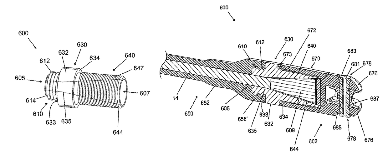
[0031]The illustrated invention is a compact, corrosion resistant termination connector that can securely connect to an end of a metallic wire rope, where the termination connector isolates the end of the metallic wire rope from electric currents and corrosive environments, such as salt water and air. As shown in FIG. 1, the termination connector 600 has three sections. The first section 610 is a ribbed annular stem 612 with a channel 605 with a substantially circular entrance port 614 that has a cross-sectional diameter that is large enough to accommodate the steel wire rope 14 (shown in FIG. 4). The second section 630 is substantially an abutment band 632 with a smooth surface and uniform edges 633,634 for creating sealing occlusions and a widening channel 635. The third section 640 is an elongate externally threaded spelter socket 647 with a fully widened conical channel 644. The fully widened conical channel 644 of the spelter socket 647 is accessed through the open end 607 of t...


PUM


Abstract

A corrosion resistant termination connector for connecting to a steel wire rope and a modular fitting for use on a magnetic influence minesweeping cable is provided. The connector body is made of a high strength composite material, and has a common channel. The body has three sections: A ribbed annular stem, an abutment band with uniform edges for forming sealing occlusions, and an externally threaded spelter socket with a conical channel. Strands of the wire rope are splayed and adhesively joined with a mixture of thermosetting resins forming a conical wedge that secures the rope within the conical channel. The modular fitting is screwed on the elongate socket section, and includes a pin with a thimble. A molded insular cover seals the steel wire rope and the ribbed stem.

Description

STATEMENT OF GOVERNMENT INTEREST[0001]The invention described herein may be manufactured and used by or for the Government of the United States of America for Governmental purposes without the payment of any royalties.BACKGROUND OF THE INVENTION[0002]1. Field of the Invention[0003]The present invention relates generally to a wire rope termination connector, and in particular to a wire rope termination connector for terminating a core wire rope in a coaxial cable, such as a minesweeping magnetic influence cable, where the core wire rope is a strength member that is subject to corrosion, including salt water, such as seawater, conducting a current. The invented termination connector is resistant to corrosion, typically environmentally isolates the strength member, typically electrically insulating, and adaptable for a variety of modular fittings that include metal such as stainless steel and polymeric materials such as engineering plastics.[0004]2. Prior Art[0005]There are many types ...

Claims


Application Information

Patent Timeline
IPC IPC(8): H02G15/02
CPCH02G15/025B63G7/04
Inventor SOVEL, JAMES E.
Owner USA REPRESENTED BY THE SEC OF THE NAVY
Learn More