Multistage turbine rotor

A turbine rotor and disk technology, which is used in gas turbine devices, blade support elements, jet propulsion devices, etc., can solve problems such as low reliability, disk damage, and disk failure.

Active Publication Date: 2018-07-06
奥德克航空发动机股份公司
View PDF3 Cites 2 Cited by
  • Summary
  • Abstract
  • Description
  • Claims
  • Application Information

AI Technical Summary

Problems solved by technology

[0005] The disadvantage of the known structure, considered a prototype, is its low reliability, since the elastic members are in contact with the disc hub or the web, which can lead to damage of the disc in its area of ​​greatest stress and further failure of the disc

Method used


Image

  • Multistage turbine rotor
  • Multistage turbine rotor

Examples


Embodiment Construction

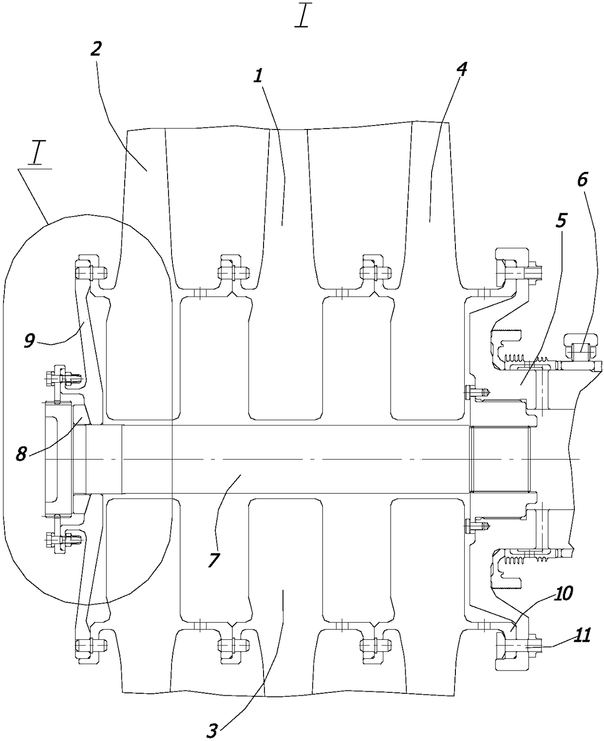
[0020] The multi-stage turbine rotor 1 comprises a first disc 2 , an intermediate disc 3 and a final disc 4 , which overhang the shaft 5 of the rotor 1 against a bearing 6 and pass through the center of a spherical washer 8 and an elastic member 9 Tension bolt 7 is connected. The last disc 4 with a radial flange 10 leading to the bearing 6 is attached to the shaft 5 by a bolt joint 11 .

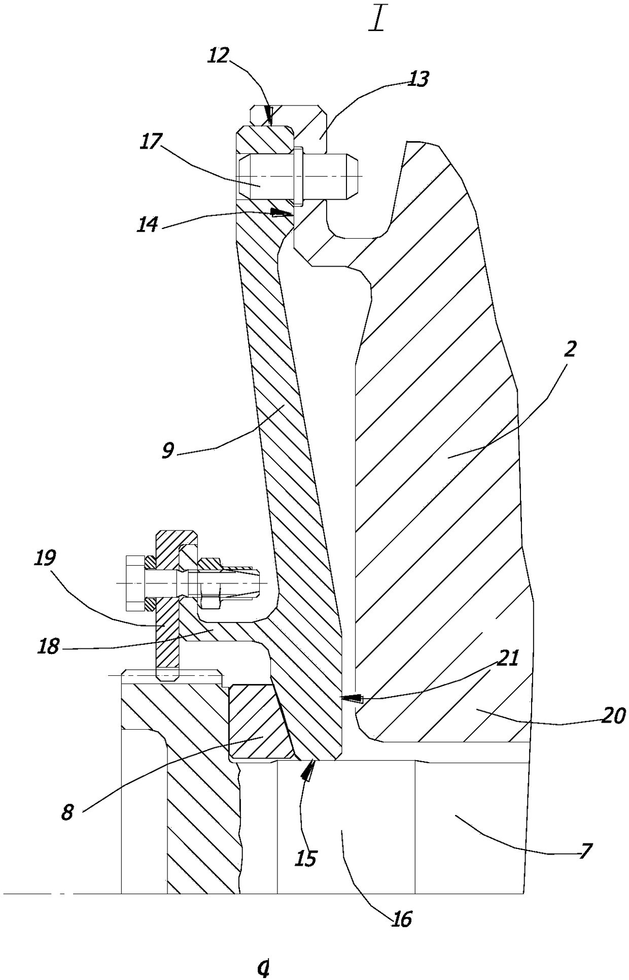
[0021] The elastic member 9 with the outer surface 12 is mounted in the Z-shaped front flange 13 of the first disc 2 and is in contact with the end face 14 of the front flange 13, while the inner surface 15 of the elastic member 9 is in contact with the main body of the tension bolt 7 16 contacts. The elastic member 9 is fixed circumferentially against the front flange 13 of the first disc 2 with an axial pin 17 and is manufactured with an L-shaped annular flange 18 on which the tension bolt 7 is mounted. Circumferential retainer 19.

[0022] The surface 21 of the elastic member 9 adjacent...


PUM


Abstract

The invention relates to multistage turbines rotors comprising first, middle and last discs, which are connected through the spherical washer and elastic element tightened with the shaft by the central clamping bolt. The elastic member is inserted into the Z-shaped front flange of the first disc at its outer surface and brought into contact with the end surface; the inner surface is mounted on thetension bolt; the front flange abutting the first disc is circumferentially fixed with an axial pin; an L-shaped annular flange is manufactured which comprises a tension bolt retainer circumferentially mounted thereon; at the same time, the surface of the elastic member adjacent to the first disk hub is made flat. According to the embodiment of hte invention and the known characteristics of the invention, the reliability of the multi-stage turbine rotor of the gas turbine engine is thus improved by preventing the elastic member from contacting the disk hub and web during operation of the rotor assembly within the gas powered turbine.

Description

technical field [0001] This invention relates to multi-stage turbine rotor assemblies within commercial and land-based gas turbine engines. Background technique [0002] Gas turbine engine rotors are known in which the first, middle and last discs are axially fixed by means of tension bolts and mounting flanges (patent RU 2 251 010, IPC F02K3 / 06, date of publication: 20 April 2005 day). [0003] Such a configuration suffers from a lack of reliability due to the relatively high stresses applied to the possibly bent tension bolts. [0004] The closest to the claimed version and believed to be the prototype is the GT engine multi-stage turbine rotor comprising a disc axially secured by tension bolts consisting of spherical washers and elastic members such as mounted in series on the bolt Belleville spring washer between head and disc hub (patent RU2 230 195, IPC F02K3 / 06, publication date: April 20, 2005). [0005] The disadvantage of the known structure, considered a protot...

Claims


Application Information

Patent Timeline
IPC IPC(8): F01D5/06
CPCF01D5/06F01D5/066F02C7/36
Inventor 弗拉基米尔·米哈维洛维奇·亚兹夫谢尔盖·伊万诺维奇·法捷耶夫弗拉基米尔·康斯坦丁诺维奇·索契夫瓦列里·阿列克谢维奇·库兹涅佐夫
Owner 奥德克航空发动机股份公司
Why Eureka
Try Eureka