
Guide wire with soldered multilayer coil member

a multi-layer coil and guide wire technology, applied in the field of guide wires, can solve the problems of difficulty in transmitting torque at the distal end of the guide wire, and achieve the effects of improving pushability, torque transmission, and tactile respons

Active Publication Date: 2012-03-15
ABBOTT CARDIOVASCULAR
View PDF3 Cites 29 Cited by
  • Summary
  • Abstract
  • Description
  • Claims
  • Application Information

AI Technical Summary

Benefits of technology

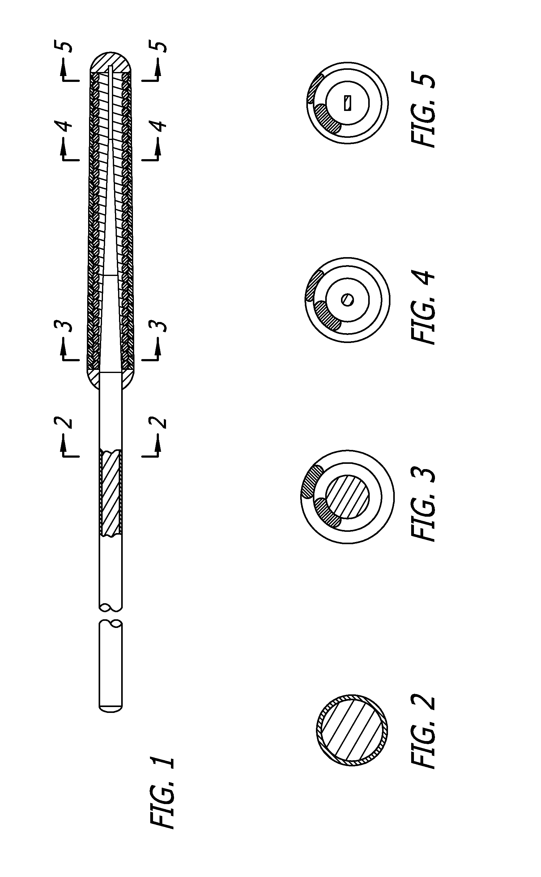
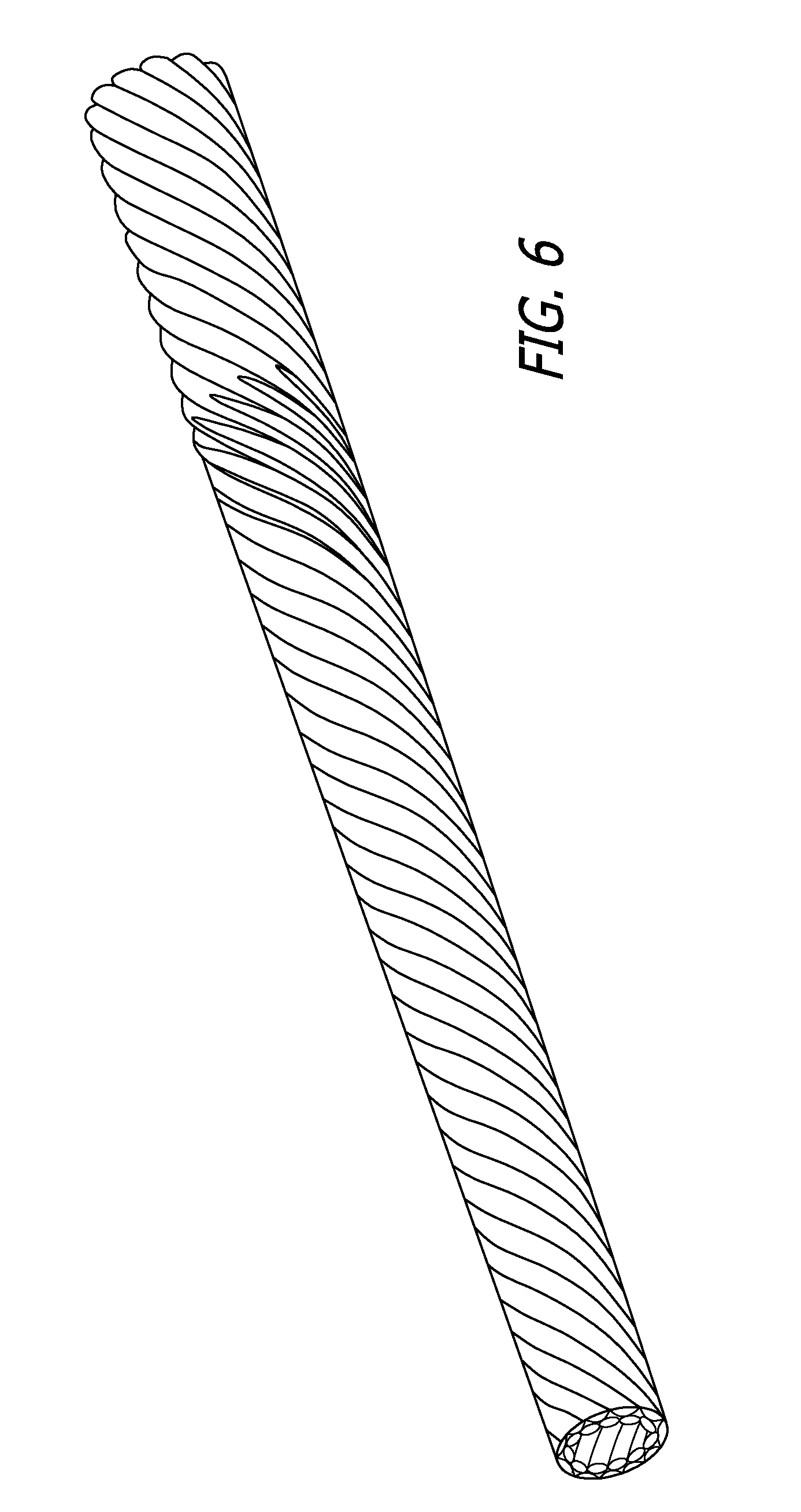
[0008]A guide wire of the present invention has a flexible coil section that is fashioned from a tube made of helically wound strands of metal such as stainless steel wire forming a first layer that is soldered to a wire coil serving as a second layer, where the multi-layer construction of the inner and outer layers leaves open a hollow center channel for insertion of a core member. In one preferred embodiment of the present invention, the multi-layer flexible coil section is mechanically ground down to either a constant or tapered outer diameter by removing selected material from the flexible coil section for desired stiffness and flexibility. The result is a guide wire that has a variable diameter flexible coil section at the distal section of the guide wire for improved pushability, torque transmission, and tactile response.

Problems solved by technology

One of the difficulties with conventional coil guide wires is that it is difficult to transmit torque at the distal end of the guide wire.
With conventional coils this can sometimes be difficult.

Method used


Image

  • Guide wire with soldered multilayer coil member
  • Guide wire with soldered multilayer coil member
  • Guide wire with soldered multilayer coil member

Examples


Embodiment Construction

[0024]A guide wire typically includes a flexible wire positioned in an organ, vessel, or duct of a patient for the purpose of directing passage of a larger device threaded over or along the length of the guide wire to a desired location in the vasculature of the patient. A wide variety of guide wires have been developed for various applications including medical applications, such as, but not limited to, coronary angioplasty. Also, endovascular interventions are rapidly advancing as a viable alternative for invasive vascular surgery. During these interventions, a guide wire is generally inserted into a region of a patient, such as the groin region, and the guide wire is then advanced to a desired location, typically under fluoroscopic guidance. Accurate positioning of the guide wire with respect to the vasculature is a prerequisite for a successful procedure. Furthermore, during neuro-interventions, positioning the guide wire accurately is difficult due to the complexity of the vasc...


PUM


Abstract

A guide wire includes an elongate core section and a flexible member disposed on the distal end, the flexible member including a first wire wound into an inner helical coil in a first direction and a second wire wound into an outer helical coil wrapped about the first helical coil in the opposite direction. The two combined helical coils add stiffness and torque transmission to the guide wire without sacrificing tactile feedback.

Description

BACKGROUND[0001]This invention relates to the field of guide wires for advancing intraluminal devices such as stent delivery catheters, balloon dilatation catheters, atherectomy catheters and the like within a patient's body, such as within a patient's vasculature.[0002]In a typical percutaneous procedure in a patient's coronary system, a guiding catheter having a preformed distal tip is percutaneously introduced into a patient's peripheral artery, e.g. femoral, radial or brachial artery, by means of a conventional Seldinger technique and advanced therein until the distal tip of the guiding catheter is seated in the ostium of a desired coronary artery. There are two basic techniques for advancing a guide wire into the desired location within the patient's coronary anatomy, the first is a preload technique which is used primarily for over-the-wire (OTW) devices and the bare wire technique which is used primarily for rail type systems. With the preload technique, a guide wire is posit...

Claims


Application Information

Patent Timeline
Patent Type & Authority Applications(United States)
IPC IPC(8): A61M25/09
CPCA61M25/09A61M2025/0915A61M2025/09091A61M2025/09083
Inventor NELSON, III, JOHN J.BURKETT, DAVID H.CORNISH, WAYNE E.
Owner ABBOTT CARDIOVASCULAR
Learn More