
Needle biobsy imaging method

a biopsy and needle technology, applied in the field of needle biopsy imaging method and endoscope, can solve the problems of high blood flow to fast-growing tumors, irregular and hyperchromic nuclei, and high oxygen and nutrient demands, so as to reduce specimen variability and reduce the cost of experimentation

Inactive Publication Date: 2012-03-15
BOARD OF RGT THE UNIV OF TEXAS SYST
View PDF8 Cites 6 Cited by
  • Summary
  • Abstract
  • Description
  • Claims
  • Application Information

AI Technical Summary

Benefits of technology

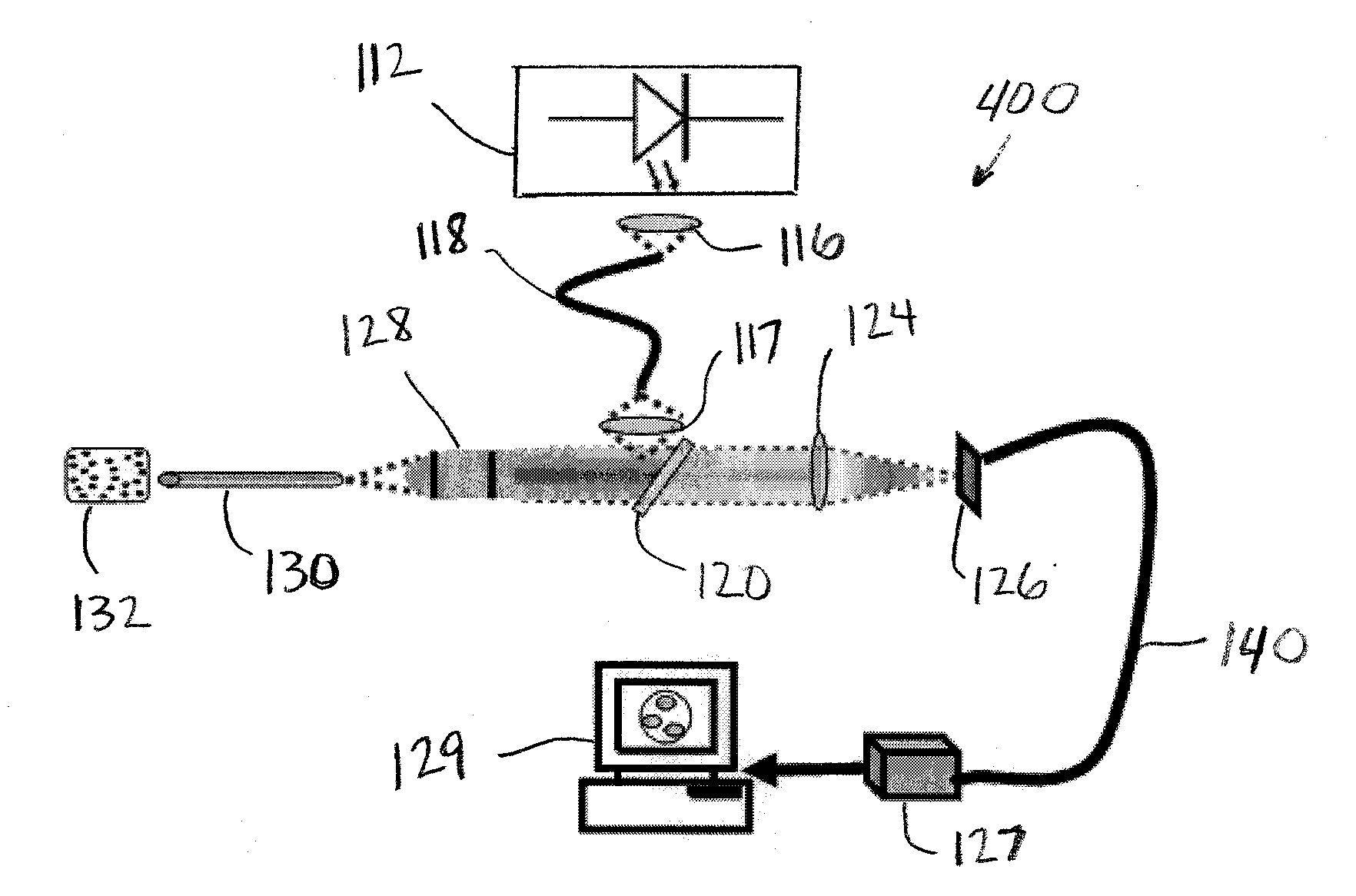
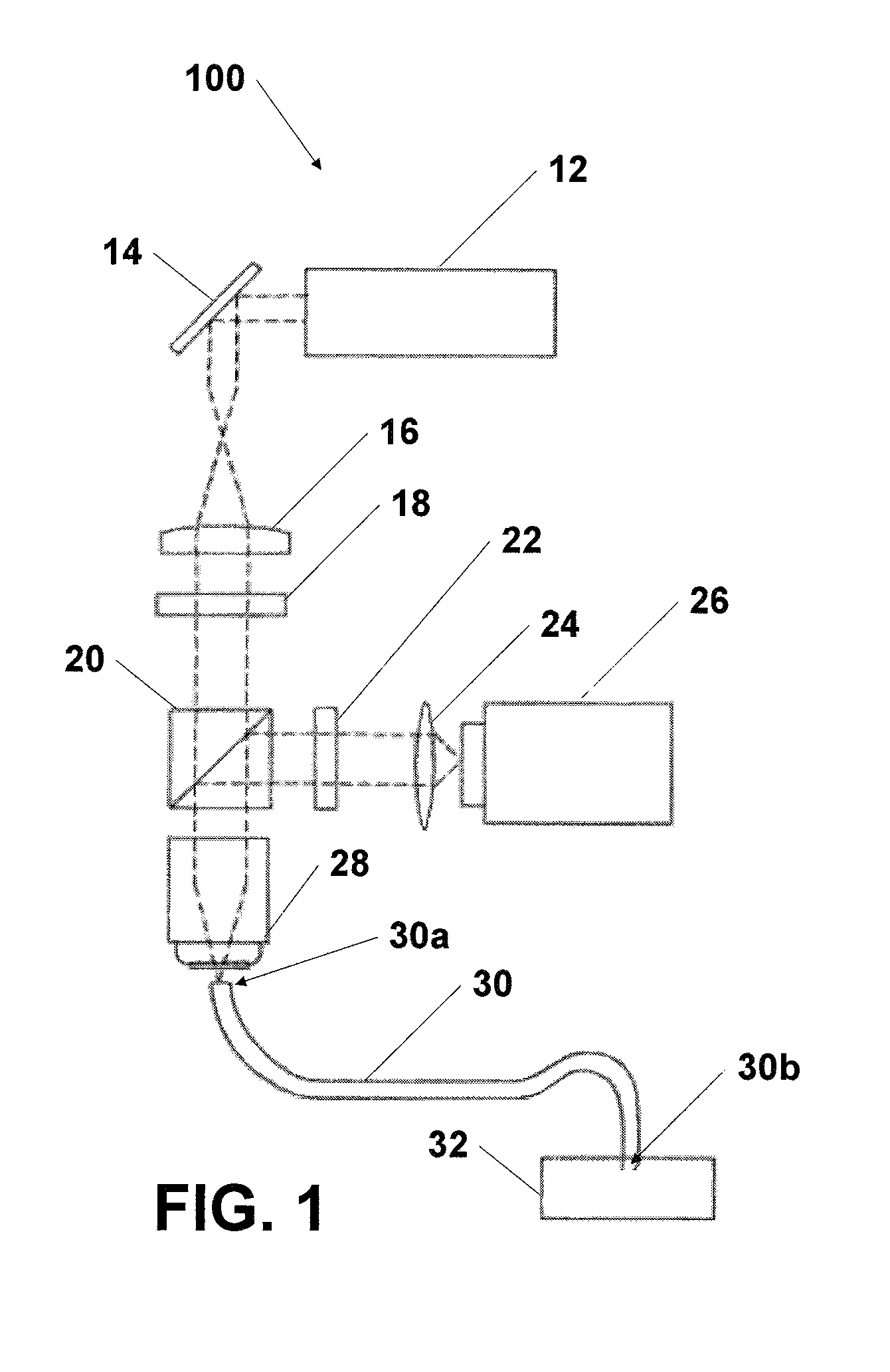
[0025]In one embodiment, a lensless fiber optic endoscope is used as an optical needle biopsy to image a layer of cells that are in contact with, or substantially in contact with, the distal tip of the endoscope. It may be used to, e.g., detect the presence of fluorophores that have labeled individual cells. In conjunction with targeted fluorophores, it is a powerful tool to immediately, or nearly immediately, detect the presence of cancer and other tissue abnormalities in vivo. One may use this technology to image tissue reflectance or other contrast agents as well. In vivo detection of many types of diseases is possible with the device. Additionally, the device is a valuable tool allowing researchers to monitor one site through time to reduce variability of specimen and to reduce the cost of experimentation.

Problems solved by technology

These nuclei often appear irregular and hyperchromic because of this abnormal DNA replication.
Mitotically active cells require a large amount of resources to be able to maintain such a high rate of replication; as a result, their oxygen and nutrient demands are very high.
Blood flow to fast-growing tumors is often increased, and frequently associated with abnormal angiogenesis.
Spectroscopic methods are unable to resolve tissues down to the cellular level, and are therefore not able to differentiate between malignant neoplasias and certain other benign conditions, such as inflammation.
Another problem, associated with biopsies used to effect a treatment, involves the need to let biopsy sites heal between biopsies, which makes ongoing treatment monitoring difficult.
Additionally, since cells removed via biopsy are removed from their surroundings, the architecture of the tissue cannot be visualized, making it more difficult to perform a pathologic diagnosis.
However, these techniques are dependant upon a chance in contrast between the two tissue types.
This leads to an increase in backscattered light from the tissue.
While these techniques are inexpensive and allow for rapid screening, their specificities are not sufficient enough to entirely replace biopsies.
Unfortunately, while a biopsy is usually a very specific technique to determine the pathologic nature of the tissue, the indicators for taking one may sometimes be misleading.
A physician may defer a biopsy from such a location because he or she believes it to be only a benign lesion, delaying treatment.
As a result of the issues associated with the procedures described above, it is sometimes desirable to perform other visual diagnostic procedures.
While magnetic resonance imaging (MRI) and computerized tomography (CT) are two widely accepted noninvasive imaging techniques, they are limited in their resolving power and are generally not able to distinguish cancerous from benign tissue at a cellular level.
Additionally, CT has the disadvantage of delivering a moderate dose of ionizing radiation to patients.
Standard microscopy generally does not work well on in vivo tissues because of the inherent turbidity present.
Despite the advantages of confocal imaging, there are drawbacks inherent in its design that limits the potential applications.
For example, since illumination must be directed into the tissues and recollected, the penetration depth of confocal microscopy is limited by how deeply the light can pass into tissues.
While longer wavelengths of light tend to scatter less and penetrate more deeply into tissues, even near infrared light (NIR) systems can only image to a depth of about 1,000 microns effectively.
Additionally, while miniaturization of confocal systems in recent years has created progressively smaller instrumentation, including a confocal endoscope, the optical and mechanical elements of these systems have generally limited the usefulness of this technique to easily accessible regions of the body.
These example shortcomings are not intended to be exhaustive, but rather are among many that tend to impair the effectiveness of previously known techniques concerning biopsies.
The techniques appearing in the art have not been altogether satisfactory, and a significant need exists for the techniques described and claimed in this disclosure.

Method used


Image

  • Needle biobsy imaging method
  • Needle biobsy imaging method
  • Needle biobsy imaging method

Examples


examples

[0087]The following examples are included to demonstrate aspects of specific experiments related to this disclosure. FIGS. 7-12 present data associated with embodiments of this disclosure. Subject matter presented as an example may be encompassed by the present claims or added to the claims to define protected subject matter.

[0088]FIG. 7 shows quantum dot (Qdot 655 nm) labeled cancer cells with broadband excitation and long pass filter at 620 nm, imaged with a needle biopsy system as described herein.

[0089]FIG. 8 shows 15 micron diameter fluorescent polystyrene spheres (produced by Invitrogen) in a 10% gelatin phantom. This image was acquired with a needle biopsy system as described here comprising a 455 nm peak emission LED (produced by Lumileds) and a 500 nm long pass filter (produced by Thorlabs).

[0090]FIG. 9 shows images of SK-BR-3 (a breast cancer cell line, from American Type Culture Collection)breast cancer cells labeled with anti-Her-2 antibody (Neomarkers) and 585 nm emissi...


PUM


Abstract

Imaging techniques. Radiation is directed from a source onto a sample using an endoscope having cellular or subcellular resolution. The endoscope includes one or more fibers. The fibers have a proximate end and a distal end, and the distal end is lensless. A focal plane of the endoscope is substantially at a tip of the distal end. Radiation from the sample is directed onto a detector to diagnose or monitor the sample.

Description

CROSS-REFERENCE TO RELATED APPLICATIONS[0001]This application is a divisional of co-pending U.S. patent application Ser. No. 11 / 464,777 filed Aug. 15, 2006, which claims priority to U.S. Provisional Application No. 60 / 708,301 filed Aug. 15, 2005. The entire text of each of the above applications is specifically incorporated herein by reference without disclaimer.STATEMENT AS TO RIGHTS TO INVENTIONS MADE UNDER FEDERALLY-SPONSORED RESEARCH AND DEVELOPMENT[0002]Aspects of this invention were made with government support of the NSF, Project Title “NSF IGERT,” Grant No. 0333080. Aspects of this invention were made with government support of the NIH, Project Title “Fiber Optic In Vivo Confocal Microscopy,” University of Texas Account No. 26-1606-76xx.BACKGROUND OF THE INVENTION[0003]1. Field of the Invention[0004]The present invention relates generally to the fields of imaging and diagnostic imaging. In one example embodiment, it concerns an endoscope which can be used as an optical needl...

Claims


Application Information

Patent Timeline
Patent Type & Authority Applications(United States)
IPC IPC(8): A61B1/07A61B1/04A61B6/00
CPCA61B1/00096A61B1/00165A61B1/0017A61B1/043A61B1/07A61B5/0068A61B5/0071A61B5/0084A61B1/0638
Inventor RICHARDS-KORTUM, REBECCAMULDOON, TIMOTHY J.SOKOLOV, KONSTANTINDWELLE, JORDAN
Owner BOARD OF RGT THE UNIV OF TEXAS SYST
Learn More