
Vertical-type heat treatment apparatus, and control method for same

a heat treatment apparatus and vertical technology, applied in vertical furnaces, lighting and heating apparatus, furnaces, etc., can solve the problems of deteriorating the controllability of internal temperature of the furnace by the use of the heater, and achieve the effect of reducing the settling time, improving throughput, and settling very accurately

Inactive Publication Date: 2012-03-15
TOKYO ELECTRON LTD
View PDF8 Cites 8 Cited by
  • Summary
  • Abstract
  • Description
  • Claims
  • Application Information

AI Technical Summary

Benefits of technology

[0011]The present invention has been made with the above problem taken into account, and an object of the invention is to provide a heat treatment apparatus and, a method for controlling the apparatus, the apparatus being able to reduce a settling time required in a heating or cooling phase or stable temperature state during use of a heater in a low-temperature region or having high heat-insulating performance, and to settle down an internal temperature of a treating vessel to a target temperature very accurately.
[0028]The present invention can reduce a settling time required for the furnace interior to recover from a heated state in a low-temperature region and settle down to the target temperature very accurately, and thus can improve throughput, or during use of a heater high in heat-insulating performance, reduce electric power consumption without affecting the throughput.

Problems solved by technology

Additionally, although energy saving in the apparatus is achievable by using a heater having high heat-insulating performance, the use of the heater deteriorates the furnace in the controllability of internal temperature.
In this case, it also becomes important how fast the furnace interior can be heated up or cooled down to a predetermined heat-treating temperature, and this issue also applies to temperatures other than those of the low-temperature region discussed above.

Method used


Image

  • Vertical-type heat treatment apparatus, and control method for same
  • Vertical-type heat treatment apparatus, and control method for same
  • Vertical-type heat treatment apparatus, and control method for same

Examples


first embodiment

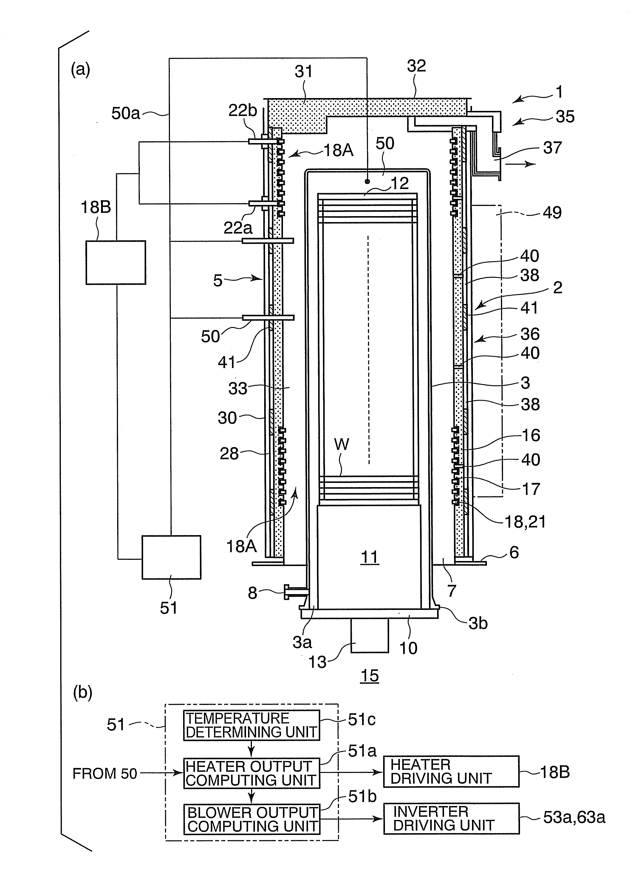
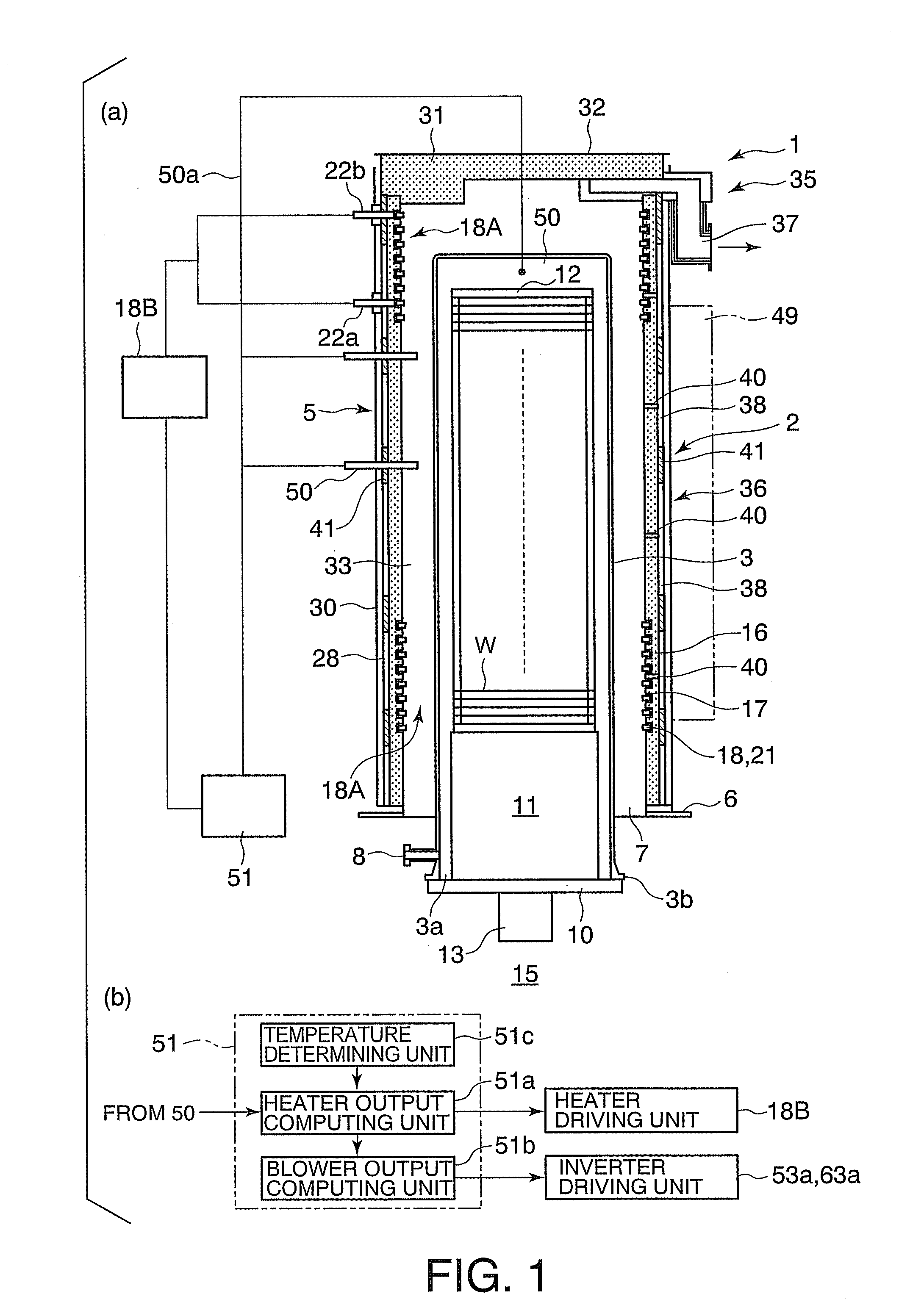
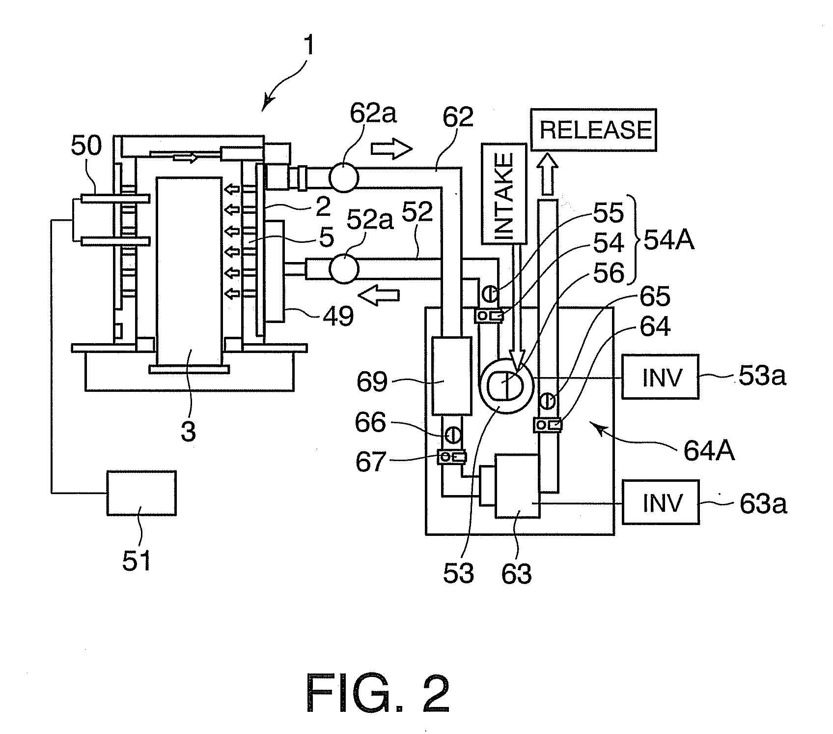
[0034]A first embodiment of the present invention is described below referring to the accompanying drawings, wherein FIG. 1(a) is a longitudinal sectional view schematically showing a heat treatment apparatus according to the first embodiment of the present invention, FIG. 1(b) is a diagram showing a controller of the heat treatment apparatus, FIG. 2 is a diagram showing a cooling medium supply line and cooling medium exhaust line of the vertical-type heat treatment apparatus, FIGS. 3(a), 3(b), and 3(c) are diagrams relating to control of the heat treatment apparatus, and FIG. 4 is a further diagram relating to the control of the heat treatment apparatus.

[0035]The vertical type of heat treatment apparatus 1 in FIG. 1(a) includes a vertical type of heat treatment furnace 2 that is able to accommodate a large number of objects to be processed, for example, semiconductor wafers W, at a time and to provide each wafer W with heat treatment processes such as oxidizing, diffusing, and / or c...

second embodiment

[0092]The following describes a second embodiment of the present invention with reference to FIG. 5.

[0093]The second embodiment shown in FIG. 5 differs only in a configuration of a controller 51, with substantially all other configurational aspects being substantially the same as in the first embodiment of FIGS. 1 to 4.

[0094]In the second embodiment of FIG. 5, the same elements as in the first embodiment of FIGS. 1 to 4 are each assigned the same reference number or symbol, and detailed description of these elements is omitted.

[0095]As shown in FIG. 5, the controller 51 includes a heater output computing unit 51a for determining heater output level to be obtained during temperature regulation with a heater 18A only, based on a furnace internal temperature detected by a temperature sensor 50 and a temperature preassigned by a temperature determining unit 51c. The controller 51 also includes a blower output computing unit (cooling output computing unit) 51b for determining a blower ou...


PUM


Abstract

A heat treatment apparatus and control method enabling the apparatus to settle down the internal temperature of a treating vessel to a target temperature accurately and quickly. The apparatus includes a furnace body with a heater on an inner circumferential surface thereof, a treating vessel disposed inside the furnace body, a cooling medium supply blower and cooling medium release blower connected to the furnace body, and a temperature sensor provided inside the treating vessel. A signal from the temperature sensor is sent to a heater output computing unit of a controller. The computing unit determines a heater output level to be obtained during temperature regulation with the heater only, the heater output level being based on a preset temperature that has been determined by a temperature determining unit and temperature detected by the temperature sensor. A blower output computing unit activates blower output based on the heater output level.

Description

CROSS-REFERENCE TO RELATED APPLICATIONS[0001]This patent application benefits from Japanese Patent Application No. 2010-200201, filed on Sep. 7, 2010, the disclosure of which is hereby incorporated by reference in its entirety.BACKGROUND OF THE INVENTION[0002]1. Field of the Invention[0003]The present invention relates to a vertical-type heat treatment apparatus and a control method for the same.[0004]2. Description of the Related Art[0005]During the manufacture of semiconductor devices, various types of heat treatment apparatuses are used to conduct oxidizing, diffusing, chemical vapor deposition (CVD), annealing, and / or other heat treatment processes, upon materials to be heat-treated, such as semiconductor wafers. Among these apparatuses is known a vertical-type heat treatment apparatus capable of heat-treating a large number of sheets at a time. This conventional vertical-type heat treatment apparatus includes a quartz-made treating vessel having an opening in its lower portion,...

Claims


Application Information

Patent Timeline
Patent Type & Authority Applications(United States)
IPC IPC(8): F27D19/00F27D7/00F27D11/02F27B1/24
CPCF27B17/0025H01L21/67248H01L21/67109
Inventor YOSHII, KOJIYAMAGUCHI, TATSUYAWANG, WENLINGSAITO, TAKANORI
Owner TOKYO ELECTRON LTD
Learn More