Drilling apparatus

Active Publication Date: 2012-03-15
JFK EQUIP
View PDF1 Cites 4 Cited by
  • Summary
  • Abstract
  • Description
  • Claims
  • Application Information

AI Technical Summary

Benefits of technology

[0028]Preferably, the first connection valve and second connection valve comprise a first connection valve seal and a second connection valve seal respectively which are configured to minimise hydraulic fluid loss during connection and disconnection of each drill rod.

Problems solved by technology

The transmission of percussion shock waves through a series of rods creates limitations as to hole depth and / or drilling accuracy, especially in larger hole sizes, as well as reliability issues.
Such drilling systems are typically energy inefficient and slow compared to hydraulic top hammer drill systems, especially in smaller hole sizes and / or shallow depths.
However these systems have not found widespread use as they suffer from reliability and economic constraints, by using a non-lubricating and potentially corrosive medium (i.e. water) to transmit energy to the percussion mechanism.
While the use of an oil powered hammer improves the energy efficiency and reliability of drilling, the arrangements disclosed in these documents suffer from the disadvantage that the external hoses are prone to damage when the hammer is in operation down a hole with resulting unreliability and reduced efficiency in terms of loss of oil and increased operational costs.
Operational efficiency is also adversely affected by the complication of reattaching the hydraulic hoses when adding and removing drill rods.
A further source of oil loss with known oil powered drill systems, such as those disclosed in U.S. Pat. No. 5,375,670 and WO96086332, is during coupling and uncoupling of the rods supplying oil under pressure to, and receiving return oil from, the hammer during travel into and out of the drilled hole.
Further loss in efficiency of known hydraulic drill systems, such as that disclosed in JP06313391, can be due to a reduction in impact energy produced and / or reduced cycle speed where the hydraulic accumulator, used to accommodate the varying flow requirements during a cycle of piston extension and retraction, is mounted remotely from the hammer.
A further disadvantage with known hydraulic drill systems is that they are expensive to manufacture and replace when damaged due to the one-piece design of the hammer.

Method used


Image

  • Drilling apparatus
  • Drilling apparatus
  • Drilling apparatus

Examples


example 1

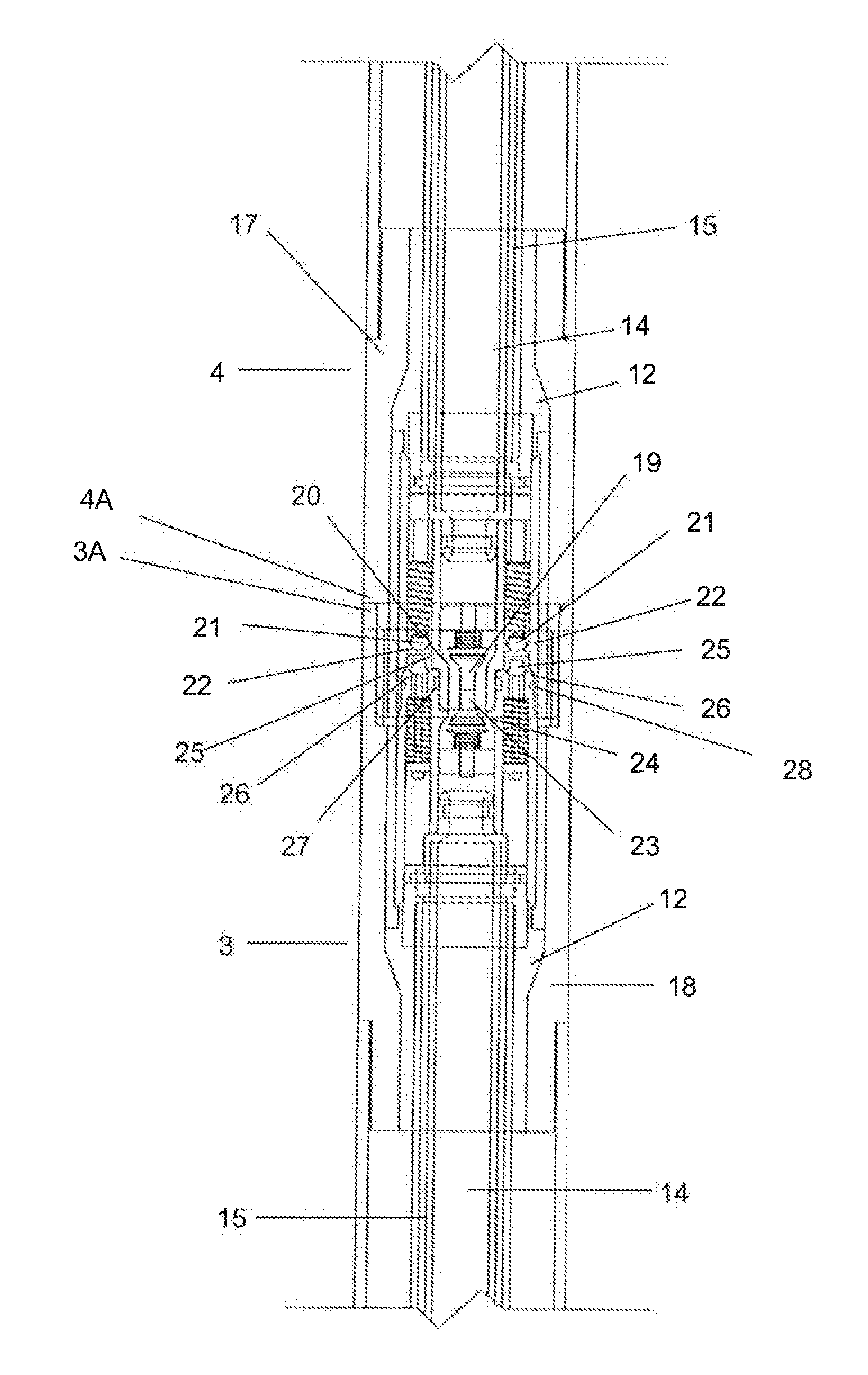
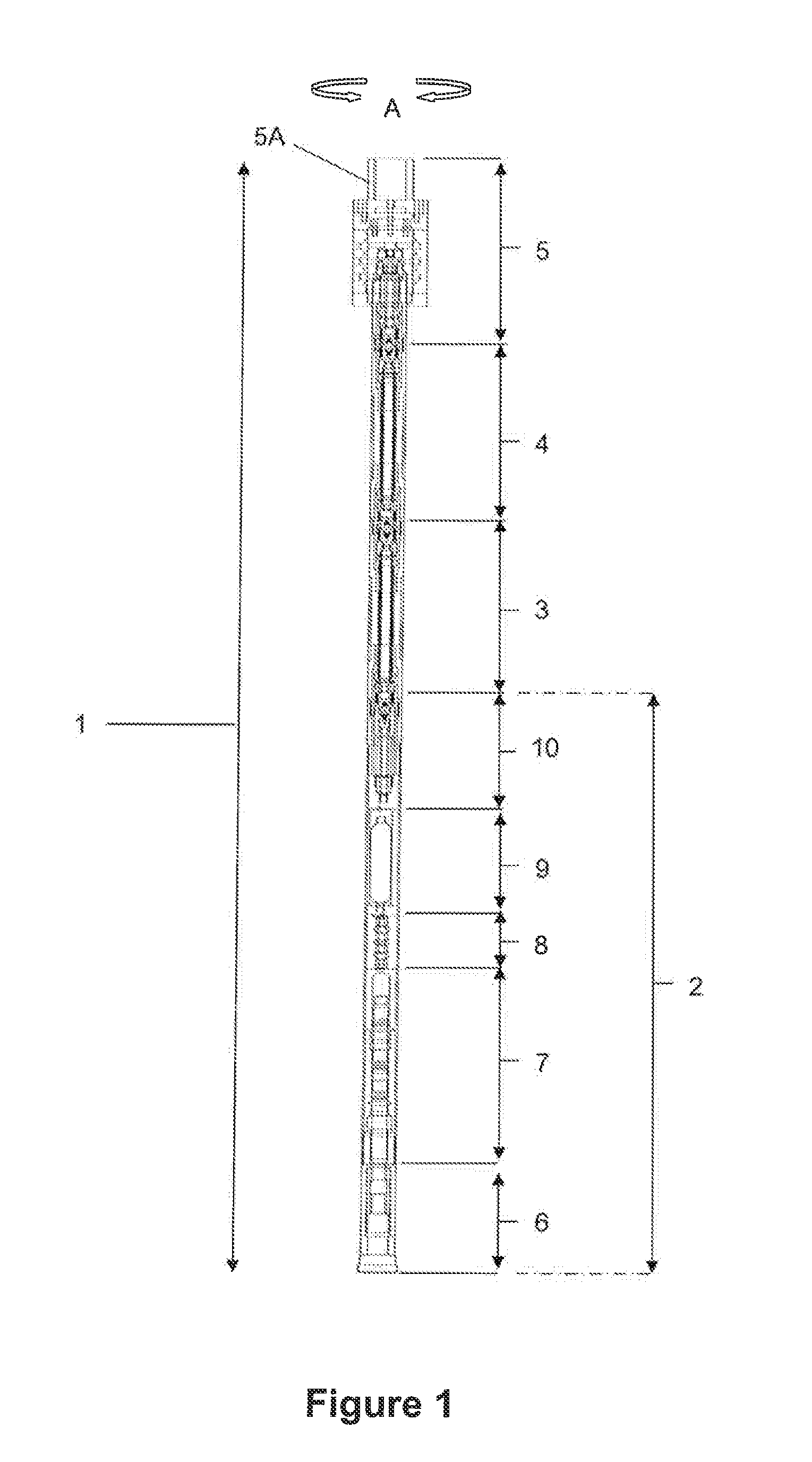
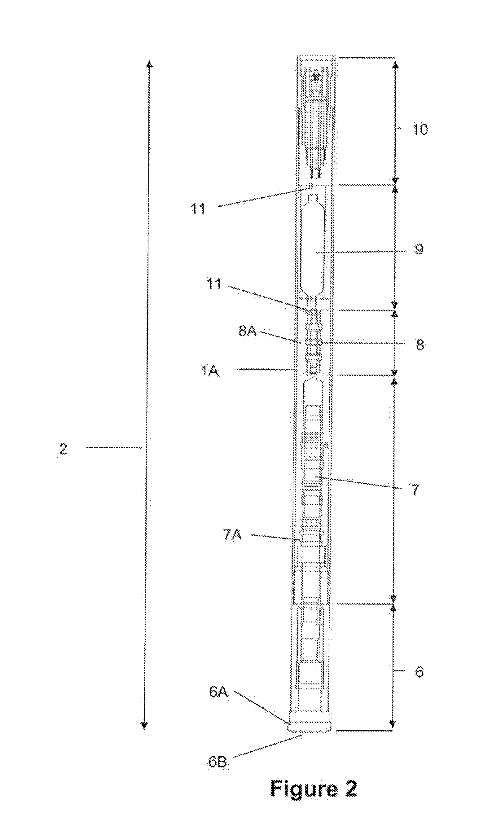
[0098]The apparatus (1) has been trialled by drilling 105 mm diameter holes in hard limestone at a penetration rate of over 1 m / min. Reliable drilling was demonstrated with a minimum loss of hydraulic oil.

example 2

[0099]Testing on prototype versions of the apparatus (1) show's that oil loss is typically as low as 0.008 litre per connection / disconnection.

[0100]Thus, preferred embodiments of the present invention may have a number of advantages over the prior art which can include:[0101]improved fuel efficiency through efficient energy transmission, recycling oil with minimal oil loss with resulting reduction in operational costs and reduced impact on the environment;[0102]improved mechanical efficiency through faster response time to changes in oil pressure during a cycle of operation with resulting faster drilling to penetrate a terrain;[0103]failsafe contamination protection of oil from drilling debris (cuttings);[0104]failsafe contamination protection of cuttings from oil (important in mineral sampling applications);[0105]improved wear of connection valves and seals and resulting improved reliability in connecting and disconnecting the components of the drilling apparatus;[0106]improved rel...


PUM


Abstract

A drilling apparatus including a hydraulically powered hammer having a piston to impact a drill bit; a shuttle valve to control reciprocation of the piston; and an accumulator for hydraulic fluid; at least one drill rod having a first connection valve for connection of the drill rod to the connection valve of the hammer; and a second connection valve for connection of the drill rod to the first connection valve of a like drill rod or to a rotation device. The piston and shuttle valve are positioned substantially in-line to the axis of movement of the hammer. The accumulator is positioned proximate to the shuttle valve; and the first connection valve, and second connection valve having at least one poppet valve positioned proximate to a corresponding valve seat.

Description

PRIORITY CLAIM[0001]This application is a continuation-in-part application of PCT Application No. PCT / NZ2009 / 000197, filed on Sep. 17, 2009.STATEMENT OF CORRESPONDING APPLICATIONS[0002]The present invention is based on the provisional specification filed in relation to Australian Patent Application No. 2008904823, the entire contents of which are incorporated herein.TECHNICAL FIELD[0003]This invention relates to a drilling apparatus. More particularly, this invention relates to a hydraulic “down-the-hole” (DTH) percussion drilling apparatus for drilling holes in a terrain.BACKGROUND ART[0004]Traditionally drilling holes into and through high strength rock types has been most economically performed by percussive drilling systems. These systems fall into one of two categories; either those where the percussion mechanism is located out of the hole (top hammer systems), or those where the percussion mechanism is located in the hole (DTH systems). Top hammer systems require the use of a ...

Claims


Application Information

Patent Timeline
IPC IPC(8): E21B7/00E21B4/14
CPCE21B4/14
Inventor KOSOVICH, JOHN
Owner JFK EQUIP
Why Eureka
Try Eureka