
Ignition device for internal combustion engine

a technology for internal combustion engines and ignition devices, which is applied in the direction of machines/engines, installations with induction energy storage, other installations, etc., to achieve the effect of improving the function of a power circuit and accelerating the charging speed of a pj capacitor

Inactive Publication Date: 2012-03-15
MITSUBISHI ELECTRIC CORP
View PDF9 Cites 4 Cited by
  • Summary
  • Abstract
  • Description
  • Claims
  • Application Information

AI Technical Summary

Benefits of technology

[0012]The present invention has been made to solve the aforementioned problem, and an object of the present invention is to provide an ignition device for an internal combustion engine which improves a function of a power circuit of a plasma ignition system, which accelerates the charging speed of a PJ capacitor in the case when a high breakdown voltage switch is turned ON and can charge the PJ capacitor to a target charging voltage within a predetermined time even in the case where a charging time period of the PJ capacitor is short and a capacitance value thereof is large.
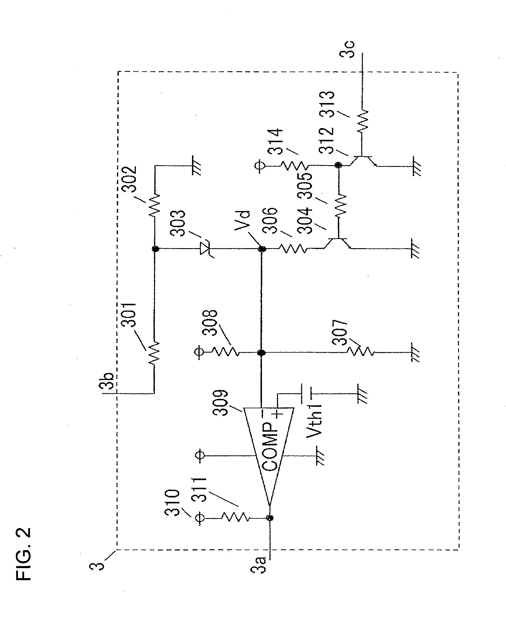
[0013]Furthermore, another object of the present invention is to provide an ignition device for an internal combustion engine in which a voltage limiting value of a tank capacitor at the time when a high breakdown voltage switch is OFF is set in multiple steps, whereby the voltage limiting value of the tank capacitor is switched in response to engine rotational frequency, operation time of a DC / DC converter in a power circuit is reduced during low rotation, and circuit consumption current and heat generation can be suppressed.
[0016]According to an ignition device for an internal combustion engine of the present invention, the charging speed of a PJ capacitor in the case when a high breakdown voltage switch is turned ON can be accelerated and a PJ capacitor can be charged to a target charging voltage within a predetermined time even in the case where a charging time period of the PJ capacitor is short and a capacitance value thereof is large.
[0017]Furthermore, a voltage limiting circuit sets a voltage limiting value at the time when a high breakdown voltage switch is OFF in multiple steps and switches the voltage limiting value in response to engine rotational frequency; whereby operation time of a DC / DC converter in a power circuit can be reduced during low rotation and circuit consumption current and heat generation can be suppressed.

Problems solved by technology

Furthermore, the voltage limiting circuit sets the voltage limiting value at the time when the high breakdown voltage switch is OFF in multiple steps and switches the voltage limiting value in response to engine rotational frequency.

Method used


Image

  • Ignition device for internal combustion engine
  • Ignition device for internal combustion engine
  • Ignition device for internal combustion engine

Examples


embodiment 1

Preferred Embodiment 1

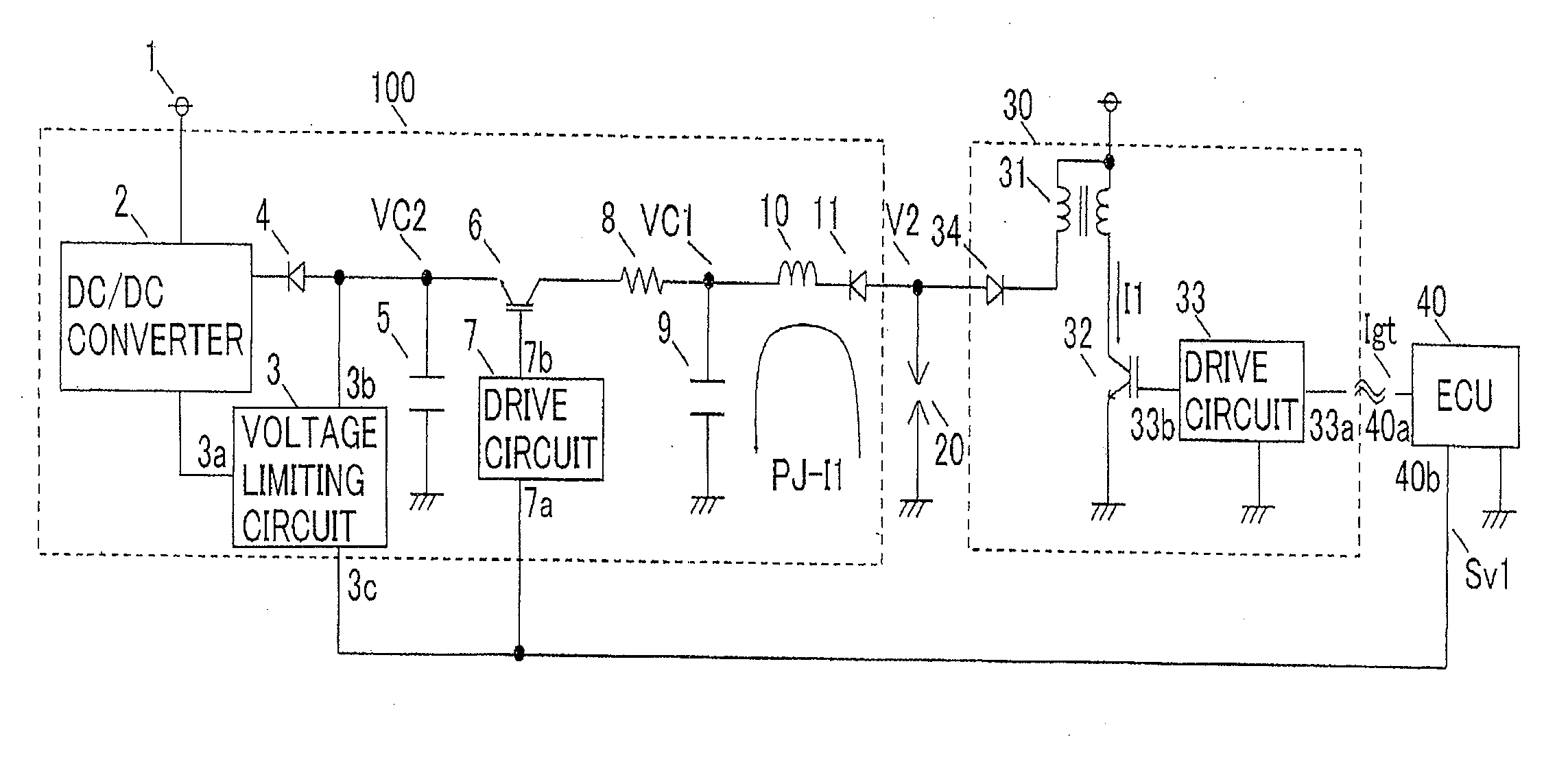
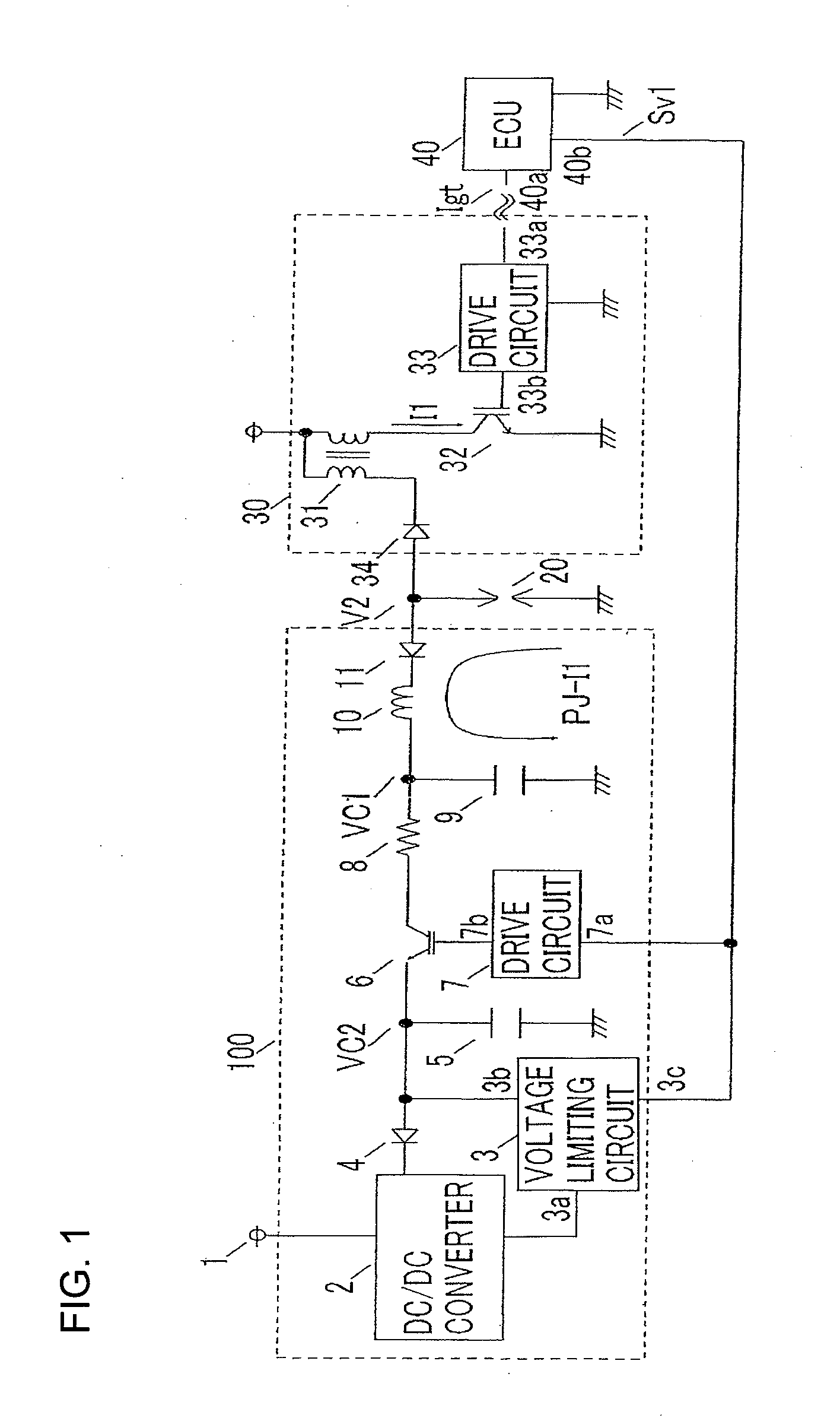
[0031]FIG. 1 is a circuit configuration diagram of an ignition device for an internal combustion engine of a preferred embodiment 1 of the present invention. In the drawing, the ignition device for the internal combustion engine of the preferred embodiment 1 is composed of a spark plug 20, an ignition circuit 30 which generates a high voltage on the basis of an ignition signal Igt from an electronic control unit (referred to as “ECU”) 40 in order to generate discharge in discharge space of the spark plug 20, and a power circuit 100 which generates a plasma current PJ-I1 in order to eject plasma by giving plasma energy to discharge space where impedance is lowered due to starting of discharge.

[0032]The ignition circuit 30 and the power circuit 100 are connected in parallel to each other with respect to the spark plug 20.

[0033]The power circuit 100 that is a major portion of the present invention includes a DC / DC converter 2, a voltage limiting circuit 3, a recti...

embodiment 2

Preferred Embodiment 2

[0057]In an ignition device for an internal combustion engine of a preferred embodiment 2 of the present invention, a voltage signal Sv1 outputted from an ECU 40 serves as an ignition signal Igt in the configuration of the preferred embodiment 1 in FIG. 1, and a timing chart at each operating point of the preferred embodiment 2 is shown in FIG. 4. Incidentally, the principle of operation is the same as that of the aforementioned preferred embodiment 1 and therefore description thereof will not be repeated.

[0058]Also in the preferred embodiment 2, as in the preferred embodiment 1, there is an effect that the charging speed of a PJ capacitor in the case when a high breakdown voltage switch is turned ON can be accelerated without changing a target charging voltage (target PJ energy) of the PJ capacitor 9.

embodiment 3

Preferred Embodiment 3

[0059]FIG. 5 is a circuit configuration diagram of an ignition device for an internal combustion engine of a preferred embodiment 3 of the present invention.

[0060]With respect to the plasma ignition device of the preferred embodiment 1 shown in FIG. 1, a plasma ignition device of the preferred embodiment 3 is further provided with an input terminal 3d on a voltage limiting circuit 3 and an output terminal 40c on an ECU 40 and a voltage signal Sv2 is further inputted from the output terminal 40c of the ECU 40 to the input terminal 3d of the voltage limiting circuit 3; and accordingly, a voltage limiting value of a tank capacitor 5 at the time when a high breakdown voltage switch 6 is OFF is set in multiple steps (plural numbers), and this configuration is denoted as a voltage limiting circuit 3′, a power circuit 100′, and an ECU 40′. Incidentally, other configuration is the same as that of the preferred embodiment 1 and therefore description thereof will not be ...


PUM


Abstract

A power circuit, which supplies plasma energy to a spark plug, includes a DC / DC converter which charges a tank capacitor, a voltage limiting circuit which restricts an output voltage of the converter to a predetermined value, a PJ capacitor which is connected to the output side of the converter and is charged by the tank capacitor, and a high breakdown voltage switch which is connected between the PJ capacitor and the DC / DC converter and controls a charging time period of the PJ capacitor in response to operating conditions of an internal combustion engine; and the power circuit switches a voltage limiting value of the tank capacitor for charging the PJ capacitor in synchronization with a driving signal of the high breakdown voltage switch.

Description

BACKGROUND OF THE INVENTION[0001]1. Field of the Invention[0002]The present invention relates to plasma ignition devices for use in ignition of internal combustion engines and, more particularly, relates to an ignition device for an internal combustion engine equipped with a power circuit which can charge a PJ capacitor to a target charging voltage within a predetermined time even in the case where a charging time period of the PJ capacitor is short and a capacitance value thereof is large.[0003]2. Description of the Related Art[0004]A known plasma ignition system, which ejects plasma jets in a compressed air-fuel mixture, includes a tank capacitor which is for charging a plasma jet (hereinafter, only referred to abbreviated as “PJ”) capacitor and a current limiting resistor in a power circuit of a plasma ignition device and gives large ignition energy to the compressed air-fuel mixture in the case of ignition to improve ignition quality. (For example, see Patent Document 1.)[0005][...

Claims


Application Information

Patent Timeline
Patent Type & Authority Applications(United States)
IPC IPC(8): F02P3/09
CPCF02P3/096F02P3/09
Inventor AIDA, FUTOSHIOKUDA, HIROSHI
Owner MITSUBISHI ELECTRIC CORP
Learn More