Method for printing a material onto a substrate

Active Publication Date: 2012-03-15
DUPONT ELECTRONICS INC
View PDF2 Cites 9 Cited by
  • Summary
  • Abstract
  • Description
  • Claims
  • Application Information

AI Technical Summary

Benefits of technology

[0014]A method for printing a material onto a substrate includes providing a relief printing form from a photosensitive element having a photopolymerizable layer with steps, including but not limited to i) forming an in-situ mask having a plurality of openings through an area opaque to actinic radiation adjacent the photopolymerizable layer, the openings having a line screen resolution equal to or greater than 250 lines per inch; ii) exposing the photopolymerizable layer to actinic radiation through the mask openings in an environment having an inert gas and a concentration of oxygen between 190,000 parts per million (ppm) and 100 ppm; and iii) treating the element resulting from step ii) to form a relief structure having a plurality of raised surfaces with a line-screen resolution equal to or greater than 250 lines per inch. The method for printing includes applying the material to the plurality of raised surfaces; and contacting the material from the plurality of raised surfaces to the substrate thereby transferring the material to the substrate.
[0015]Another

Problems solved by technology

Although it is possible to create a relief printing form having one or more coating areas composed of a singular, raised surface element instead of the plurality of fine closely-spaced raised surface elements, transfer of the coating material by the singular raised surface element does not create a sufficiently uniform layer of the coating material in the coated regions on the substrate.
Analog workflow requires the preparation of the phototool, which is a complicated, costly and time-consuming process requiring separate processing equipment and chemical development solutions.
Presence of such foreign matter can cause lack of intimate contact between the phototool and plate as well as image artifacts.
But not all end-use applications view this dot-sharpening effect as beneficial.
However, the dot-sharpening effect associated with conventional digital exposure in the presence of atmospheric oxygen becomes a disadvantage for relief printing forms, such as the coatings plate, that need to have a relief structure that is generated by high line resolution imaging.
The magnitude of the reduction in printable dot surface area made by the conventional digital workflow is such that the plurality of raised printing elements in the coating area of the printing form are not sufficiently close enough that a uniform layer of the coating material can be formed on the substrate.
Further, the magnitude of the reduction in printable dot surface area made by the digital workflow cannot be compensated by creating larger openings in the in-situ mask because each opening would need to be larger than the dimension of a pixel associated with the desired line / dot resolution, and would overlap into the adjacent pixel.
Consequently, it is not possible by conventional digital workflow to fabricate a relief printing form that has a plurality of fine and closely-spaced, raised surface elements (i.e., dots) in a coating area sufficient to transfer a coating material and form a uniform continuous layer of the coating material on the substrate.
Thus, the need to use digital workflow in the fabrication of relief printing forms conflicts with the need for the printing form to have high line resolution raised surface elements similar to the size and proximity of the raised surface elements produced by analog workflow.

Method used


Image

  • Method for printing a material onto a substrate
  • Method for printing a material onto a substrate

Examples


example 1

[0096]Two photosensitive precursor printing elements, CYREL® photopolymerizable printing plates, type DPI (0.067 inch (0.17 cm) thickness of photopolymer and support), having a ultraviolet radiation opaque layer disposed thereon, were identically imaged by ablating the radiation opaque layer with infrared laser radiation to create an in-situ mask on the element having a range of openings (1%, 5%, 10%, 20%, 50%, 70%, 90% area opening in mask) on a CYREL® Digital Imager. Opening size was measured on one plate with a Nikon measuring microscope to estimate the actual mask opening size. The line screen resolution was 150 lines per inch. Although outside of the recited range for high-resolution printing or coating by the present method, this example demonstrated the capability of the present method (of a modified digital workflow) to create feature sizes of raised surface elements in a relief structure of a relief printing form that are only slightly smaller than the corresponding opening...

example 2

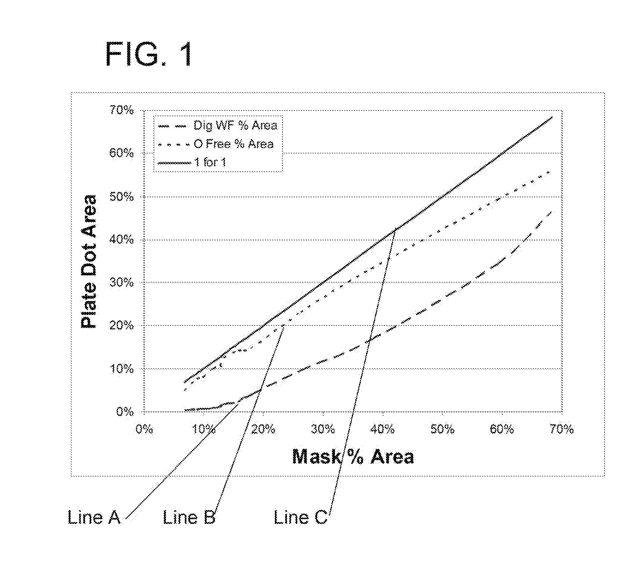
[0101]This example demonstrates a comparison of three different plate fabrication methods 1) conventional analog plate fabrication which used a film intermediate 2) conventional digital plate fabrication (digital workflow) which formed an in-situ mask and imagewise exposed through the mask in the presence of atmospheric oxygen as detailed above, and 3) a modified digital work flow plate fabrication method, which formed an in-situ mask and imagewise exposed through the mask in the presence of an inert gas, e.g., nitrogen, and with a concentration of oxygen between 190,000 and 100 ppm, as detailed above.

[0102]CYREL® photopolymerizable printing plates were used as the photosensitive precursor printing elements, which differed by the presence or absence of a radiation opaque digital layer disposed on the element, but having the same or substantially the same photopolymerizable composition forming the elastomeric layer. CYREL® photopolymerizable printing plates, type DPU (0.067 inch (0.1...

example 3

[0110]A CYREL® photopolymerizable printing element having a radiation opaque digital layer, type DPI (0.045 inch (0.114 cm) thickness of photopolymer layer and support) was used to evaluate the ability to create very small structures of the raised surface elements when prepared according to the inventive method of the modified digital workflow. The digital layer was imaged by ablation to form an in-situ mask on a CYREL® Digital Imager. The element was imaged to form the in-situ mask having multiple image patterns at resolutions of 10,000, 8,000 and 4,000 scan lines per inch and at spatial resolutions of 300, 400 and 600 DPI (dots per inch). The element was placed in an exposure chamber as described in Example 1, and imagewise exposed to actinic radiation in the presence of nitrogen as the inert gas and with a concentration of oxygen less than 1000 ppm and above 100 ppm. The exposed element was solvent processed using conventional solvent processing conditions, to form a printing pla...


PUM

PropertyMeasurementUnit
Fractionaaaaaaaaaa
Fractionaaaaaaaaaa
Fractionaaaaaaaaaa

Abstract

The invention provides a method for printing a material onto a substrate with a relief printing form made from a photosensitive element. The method includes forming an in-situ mask having a line screen resolution equal to or greater than 250 lines per inch on the photosensitive element, exposing the element to actinic radiation through the in-situ mask in an environment having an inert gas and a concentration of oxygen between 190,000 and 100 ppm, and treating the exposed element to form a relief structure having a plurality of raised surfaces with a line screen resolution equal to or greater than 250 lines per inch. Printing is accomplished by applying an imaging material to the plurality of raised surfaces and contacting to transfer the imaging material to the substrate. The method is suitable for printing high resolution graphic images, as well as for forming a uniform layer of imaging material on the substrate.

Description

BACKGROUND OF THE INVENTION[0001]1. Field of the Disclosure[0002]This invention pertains to a method for printing a material onto a substrate, and in particular, to a method of printing using a relief printing form that transfers the material from a plurality of raised surfaces upon contact to the substrate.[0003]2. Description of Related Art[0004]Flexographic printing plates are widely used for printing of packaging materials ranging from corrugated carton boxes to cardboard boxes and to continuous web of plastic films. Flexographic printing plates are used in relief printing in which ink is carried from a raised-image surface and transferred to a substrate. Flexographic printing plates can be prepared from photopolymerizable compositions, such as those described in U.S. Pat. Nos. 4,323,637 and 4,427,759. Photosensitive elements generally have a solid layer of the photopolymerizable composition interposed between a support and a coversheet or a multilayer cover element. Flexographi...

Claims


Application Information

Patent Timeline
IPC IPC(8): B41F1/18G03F7/20G03F1/00
CPCG02F1/133711G03F7/2012Y10T403/5741G03F7/202G03F7/2022G03F7/2018
Inventor RUDOLPH, MICHAEL LEE
Owner DUPONT ELECTRONICS INC
Why Eureka
Try Eureka