
Platelet aggregation using a microfluidics device

a microfluidics and platelet technology, applied in specific use bioreactors/fermenters, laboratory glassware, biomass after-treatment, etc., can solve the problems of low shear rate, tissue infarction and organ failure, vascular occlusion, etc., to facilitate the detection and observation of platelet aggregation and high throughput

Inactive Publication Date: 2012-03-08
MONASH UNIV +1
View PDF2 Cites 31 Cited by
  • Summary
  • Abstract
  • Description
  • Claims
  • Application Information

AI Technical Summary

Benefits of technology

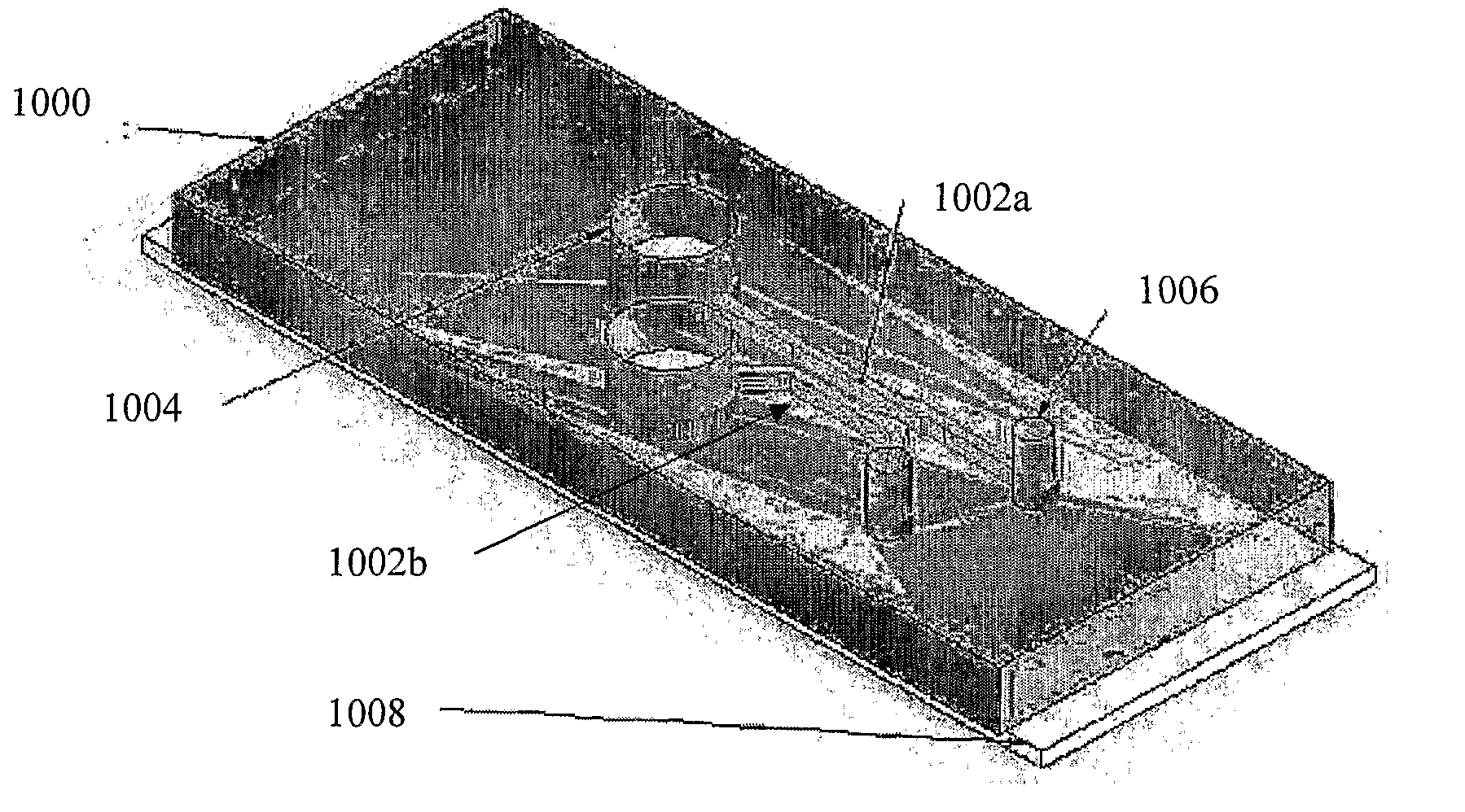
[0020]In an embodiment of the first or second aspect, a plurality of channels may be provided, each channel having a protrusion of substantially the same dimensions. In such an embodiment the detection means may be operable to detect a sum of all platelet aggregation in all the channels. In one example, the plurality of channels are arranged in parallel. Such embodiments of the invention may be advantageous in improving reliability of detection of platelet aggregation when a single sample is divided and passed through each of the plurality of channels.
[0114]It will also be appreciated that the above high throughput screening method may be advantageous as a screening tool for screening a plurality of platelet samples derived from transgenic animals such as transgenic mice for shear dependent platelet defects. The high throughput array version of the device would allow for large numbers of samples from mice that have undergone recombinant or chemical mutation to be screened rapidly for platelet defects. The method may also be used to screen samples for a large number of transgenic mice.

Problems solved by technology

Central to this process is the excessive accumulation of platelets and fibrin at sites of atherosclerotic plaque rupture, leading to vascular occlusion, tissue infarction and organ failure.
Atherosclerotic lesions typically develop at arterial branch points or curvature (i.e carotid sinus), where shear rates can be low and flow non-uniform.
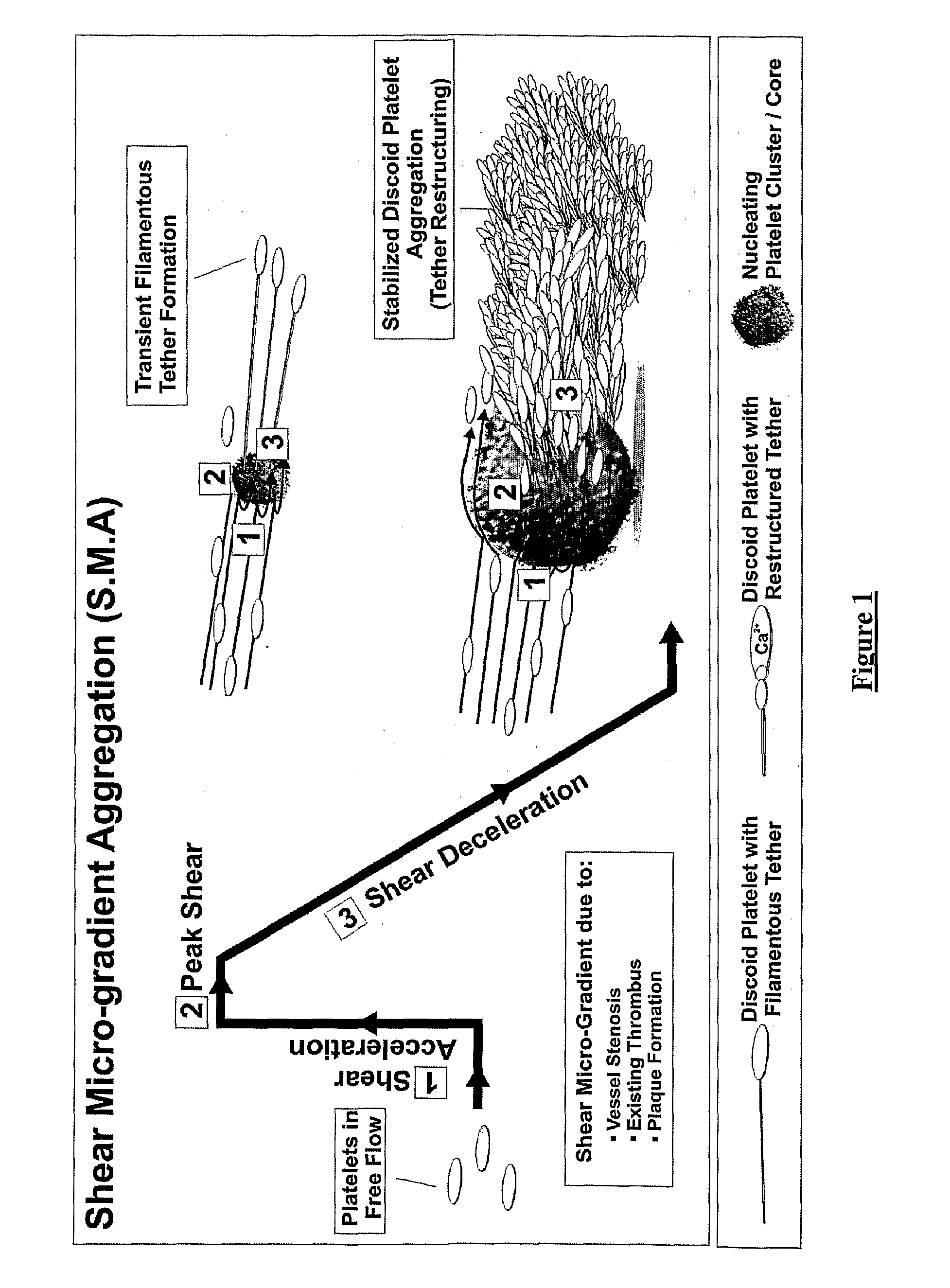
Flow velocity and shear rates can become extreme with progressive vascular occlusion, establishing a potential dangerous cycle of shear-dependent propagation of the thrombotic process.
However, the precise mechanisms by which rheological changes accelerate the atherothrombotic process remain incompletely understood.
These complex rheological conditions may significantly modulate blood platelet function.

Method used


Image

  • Platelet aggregation using a microfluidics device
  • Platelet aggregation using a microfluidics device
  • Platelet aggregation using a microfluidics device

Examples


example 1

Blood Perfusion Through a Step Geometry

[0220]FIG. 11a is a representative micrograph (40× magnification) sequence of human (hirudin anti-coagulated) blood perfusion through a micro-shear gradient device consisting of an in-flow (entry) width of 100 μm, a contraction angle (θc) of 90°, a gap height of 10 μm, an expansion angle (θe)) of 60°, and an expansion / exit width of 700 μm. The grey arrow denotes the point of initial aggregation [t=12 sec], the black arrow designates the limit of thrombus growth in the expansion zone (representative of n=3 experiments).

[0221]FIG. 11b illustrates the results produced by computational fluid dynamics (CFD) simulation (Velocity v displacement plot) showing the velocity change for a platelet (particle) travelling 1 μm (½ discoid platelet diameter) from the surface of the micro-channel wall geometry in (a). In the case of a straight microchannel segment (1,800.s−1 laminar flow), the platelet travels at constant velocity throughout its path length. The...

example 2

Flow Rate Dependency of Two Step Geometry Iterations

[0226]FIG. 12a comprises representative aggregation traces as a function of flow rate (Q=2, 4, 6 & 8 μl / min) through a micro-shear gradient device consisting of an in-flow / entry width of 100 μm, a contraction angle (θc) of 90°, gap height of 20 μm, an expansion angle (θe) of 30°, and an expansion / exit width of 700 μm.

[0227]FIG. 12b is representative aggregation traces as a function of flow rate (Q=2, 4, 6 & 8 μl / min) through a micro-shear gradient device consisting of an in-flow width of 100 μm, a contraction angle (θc) of 90°, gap height of 20 μm, an expansion angle (θe) of 90°, and an expansion width of 700 μm.

[0228]Analysis of flow rate (Q=2, 4, 6 & 8 μl / min) dependency was examined in two step geometry configurations with expansion angles of 30° and 90° (FIGS. 12a and 12b respectively). The size of the aggregates decreased significantly with decreasing flow rate below 8μl / min in the case of both geometries. There was a decrease...

example 3

Sphere Geometry

[0229]FIG. 13a comprises DIC image frames showing the nature and extent of discoid platelet aggregation at the downstream face of VWF coated sphere geometries following whole human blood (pre-treated with 100 μM MRS2179, 10 μM 2-MeSAMP and 10 μM Indomethacin) perfusion at an applied γ of 10,000.s−1 (n=5).

[0230]FIG. 13b illustrates mean discoid platelet aggregate size (surface area in μm2) as a function of the downstream low τx,y pocket (zone 3 surface area μm2) exhibiting τ≦30.4 Pa (n=3).

[0231]FIG. 13c shows mean discoid platelet aggregate size at the downstream face of 5 μm VWF coated sphere geometries at an applied bulk γ of 10,000.s−1; Control—hirudin anticoagulated whole blood; anti-αIIbβ3—hirudin anticoagulated whole blood treated for 10 minutes with 30 μg / ml c7E3 Fab prior to blood perfusion; anti-GPIb—,hirudin anticoagulated whole blood treated for 10 minutes with 50 μg / ml of the anti-GPIb blocking IgG ALMA12 (n=3).

[0232]FIG. 13d shows the results of CFD simula...


PUM


Abstract

A microfluidics device to provide real time monitoring of platelet aggregation of a biological sample obtained from a subject. The device comprises a channel configured for passage of the biological sample, the channel comprising a protrusion configured to induce an upstream region of shear acceleration coupled to a downstream region of shear deceleration and defining there-between a region of peak rate of shear, the downstream region of shear deceleration defining a zone of platelet aggregation. The device further comprises a platelet detection means for detecting aggregation of platelets in the zone of aggregation as a result of passage of the biological sample through the channel. Methods to assess real time platelet aggregation of a biological sample obtained from a subject are further described.

Description

CROSS-REFERENCE TO RELATED APPLICATIONS[0001]The present application claims priority from Australian Provisional Patent Application No 2009901033 filed on 10 Mar. 2009 and Australian Provisional Patent Application No 2009905303 filed on 29 Oct. 2009, the contents of each of which are incorporated herein by reference.TECHNICAL FIELD[0002]The present invention relates to a device that facilitates analysis of aggregation of platelets or their progenitors in a biological sample. The device induces localised and controlled disturbances in blood flow which lead to spatially controlled platelet aggregation. The present invention also relates to a method for causing platelets to aggregate in a known location so as to facilitate diagnosis of platelet function and activity. The present invention also relates to a method for controllably modulating the rate and extent of platelet aggregation. The method of the invention is particularly useful for assessing subjects for abnormalities in platele...

Claims


Application Information

Patent Timeline
IPC IPC(8): C12Q1/56C12M1/34C12Q1/34C12Q1/02
CPCB01L3/502707B01L3/502746B01L3/502761B01L3/502776G01N21/82B01L2300/1827B01L2400/0457B01L2400/0475B01L2400/086B01L2300/0654
Inventor MITCHELL, ARNAN DEANETOVAR LOPEZ, FRANCISCO JAVIERJACKSON, SHAUN PHILLIPNESBITT, WARWICK SCOTTCARBERRY, JOSIE
Owner MONASH UNIV
Learn More