Spot-welding method and spot-welding device

Active Publication Date: 2012-03-08
SUBARU CORP
View PDF9 Cites 19 Cited by
  • Summary
  • Abstract
  • Description
  • Claims
  • Application Information

AI Technical Summary

Benefits of technology

[0025]Accordingly, in view of the circumstances described above, a first object of the present invention is to provide a spot-welding method and a spot-welding device that can achieve uniform and stable weld quality when a workpiece having a three-stacked-plate structure formed by stacking a thin plate over one of two stacked thick plates is spot-welded.
[0026]A second object of the present invention is to provide a spot-welding method and a spot-welding device that can achieve uniform and stable weld quality when a workpiece having a four-stacked-plate structure formed by stacking two thin plates respectively over opposite faces of two stacked thick plates is spot-welded.

Problems solved by technology

However, the calorific value becomes excessive when the current value is too high, causing expulsion and surface flash, in which molten metal spatters, to occur between the plate materials.
Specifically, such expulsion and surface flash is an explosion phenomenon of the molten metal caused by overheating of the joint section and causes holes and cracks to form in the nugget.
This results in discontinuity in the shape of the nugget and the metallographic structure, causing a reduced thickness of the joint section as well as a significant reduction in the strength thereof.
In contrast, if the current is too low, sufficient joint strength cannot be obtained since the nugget becomes small in size.
If the applied pressure is low, the contact area between the plate materials correspondingly decreases, leading to the occurrence of expulsion and surface flash caused by overheating due to an increased current density.
On the other hand, an excessively applied pressure leads to an increase in the contact area at the joint section, resulting in a reduced current density and a reduced calorific value.
However, because the amount of weld penetration between the thin plate 101 and the first thick plate 102 is small, the weld strength is unstable.
This makes it difficult to ensure uniform weld quality.
Furthermore, using various movable electrodes 121 and fixed electrodes 122 having different tip diameters in an interchangeable manner in accordance with the thicknesses of the thin plate 101, the first thick plate 102, and the second thick plate 103 and the shape or the area of the workpiece 100 is not practical since it is extremely troublesome and can possibly lead to a significant decrease in productivity.
In addition, the preparation and management of such various movable electrodes 121 and fixed electrodes 122 having different tip diameters require a large amount of management cost.
This can possibly result in variations in the current density at the joint sections of the workpiece 100, leading to reduced spot-welding quality.
Furthermore, this method is limited to specific spot-welding devices since the method cannot be used in a spot-welding device that has an equalizing function between the base and the wrist portion of the robot for allowing for movement in response to a reaction force generated during the welding and pressing process.

Method used


Image

  • Spot-welding method and spot-welding device
  • Spot-welding method and spot-welding device
  • Spot-welding method and spot-welding device

Examples


first embodiment

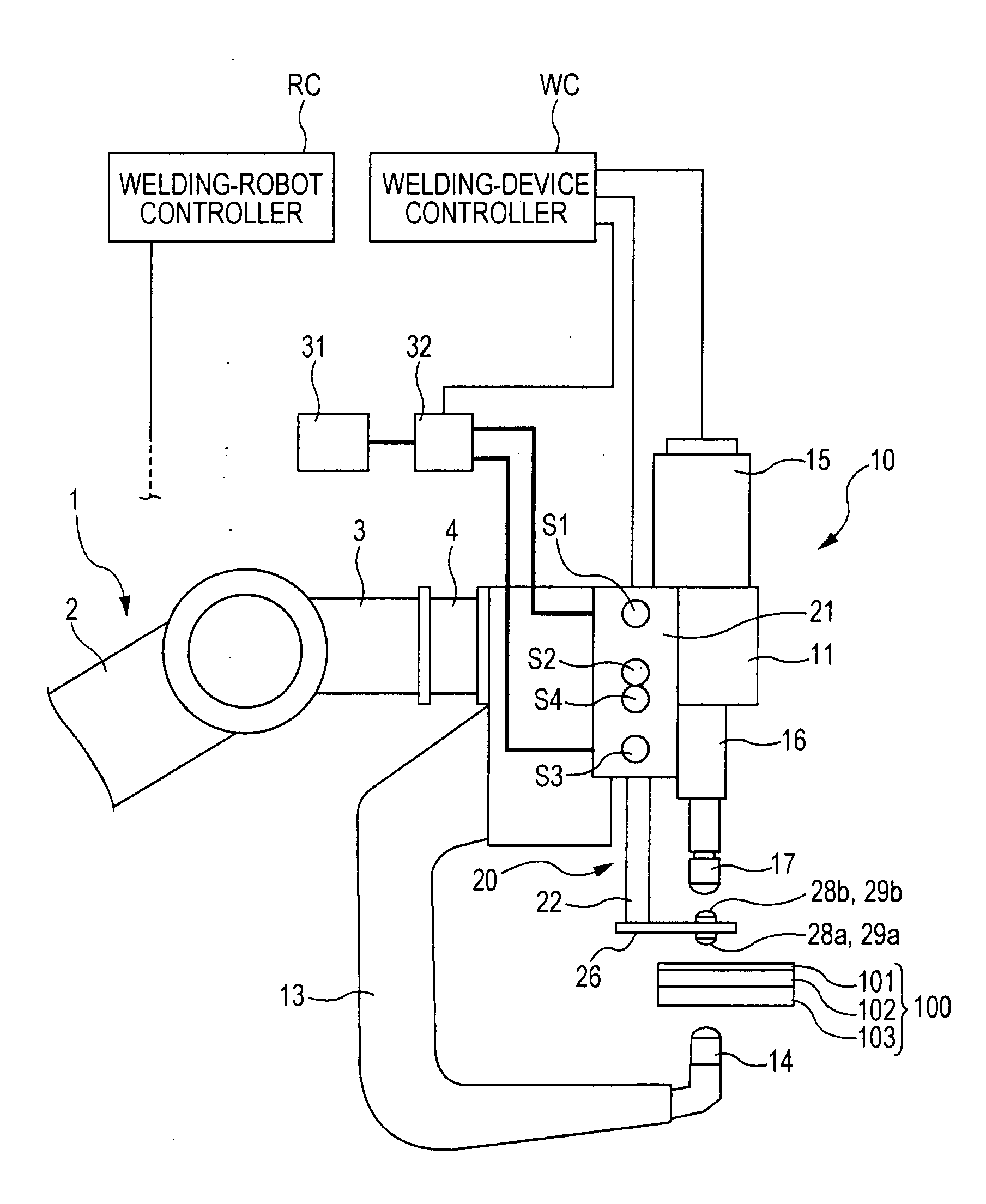
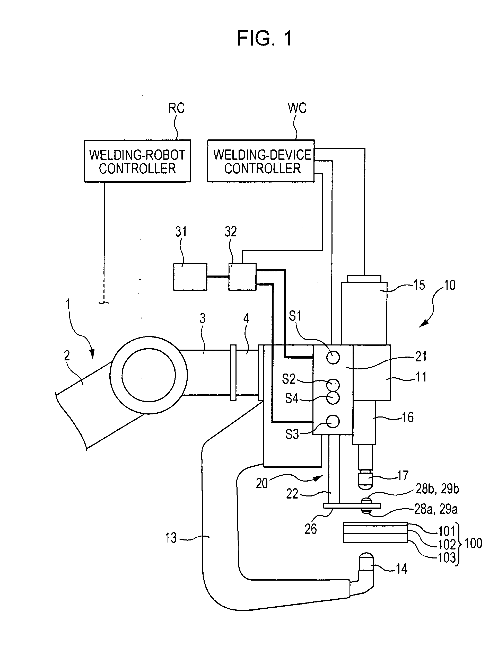
[0070]A first embodiment of the present invention will be described below with reference to FIGS. 1 to 8. FIG. 1 illustrates the configuration of a spot-welding device. FIG. 2 illustrates a relevant part of the spot-welding device.

[0071]In FIG. 1, reference numeral 1 denotes a welding robot, reference numeral 10 denotes a spot-welding device supported by the welding robot 1, and reference numeral 100 denotes a workpiece to be welded.

[0072]Before describing the welding robot 1 and the spot-welding device 10, the workpiece 100 will be described first. The workpiece 100 has a three-stacked-plate structure formed by stacking a thin plate over one of two stacked thick plates. For example, in the following order from the top, the three-stacked-plate structure includes a thin plate 101 having low rigidity, and a first thick plate 102 and a second thick plate 103 that are thicker and more rigid than the thin plate 101.

[0073]The welding robot 1 is, for example, an articulated robot and has a...

second embodiment

[0117]A second embodiment of the present invention will be described below with reference to FIGS. 9 to 11. FIG. 9 illustrates the configuration of a spot-welding device, FIG. 10 illustrates a relevant part of the spot-welding device, and FIG. 11 is an operation diagram thereof. Components in FIGS. 9 to 11 that correspond to those in FIGS. 1 and 2 are given the same reference numerals, and detailed descriptions thereof will be omitted.

[0118]In a spot-welding device 40 according to this embodiment, the control-pressure applying unit 20 in the first embodiment is replaced by control-pressure applying unit 41 supported by the rod 16.

[0119]As shown in FIGS. 9 and 10, the rod 16 of the spot-welding device 40 has a columnar shape and includes a base end 16A protruding downward from the base 11 and having a relatively large diameter, a columnar shaft 16C having a smaller diameter than the base end 16A and extending continuously from and coaxially with the base end 16A via a step 16B, and a...

third embodiment

[0126]A third embodiment of the present invention will be described below with reference to FIGS. 12 to 17. FIG. 12 illustrates the configuration of a spot-welding device, FIG. 13 illustrates a relevant part of the spot-welding device, and FIGS. 14A to 14H illustrate operation steps thereof. Components in FIGS. 12 to 14H that correspond to those in FIGS. 1 and 2 are given the same reference numerals, and detailed descriptions thereof will be omitted.

[0127]In FIG. 12, reference numeral 1 denotes a welding robot, reference numeral 50 denotes a spot-welding device supported by the welding robot 1, and reference numeral 110 denotes a workpiece to be spot-welded.

[0128]Before describing the welding robot 1 and the spot-welding device 50, the workpiece 110 will be described first. The workpiece 110 has a four-stacked-plate structure formed by stacking thin plates over opposite faces of two stacked thick plates. For example, the four-stacked-plate structure includes a first thick plate 102 ...


PUM

PropertyMeasurementUnit
Pressureaaaaaaaaaa

Abstract

When spot-welding a workpiece including a thin plate, a first thick plate, and a second thick plate, the workpiece is clamped by a fixed electrode in contact with the second thick plate, a movable electrode in contact with the thin plate, and control-pressure applying unit set adjacent to the movable electrode and in contact with the thin plate. Pressure is applied to the second thick plate by the fixed electrode, and pressure and control pressure are respectively applied by the movable electrode and the control-pressure applying unit to the thin plate. The pressure from the fixed electrode is controlled to be smaller than the pressure from the movable electrode. The current density between the thin plate and the first thick plate increases.

Description

CROSS REFERENCES TO RELATED APPLICATIONS[0001]The present application claims priority from Japanese Patent Application No. 2010-200643 filed on Sep. 8, 2010, the entire contents of which are hereby incorporated by reference.BACKGROUND OF THE INVENTION[0002]1. Field of the Invention[0003]The present invention relates to spot-welding methods and spot-welding devices for spot-welding a workpiece having a stacked-plate structure constituted of stacked plate materials having different thicknesses.[0004]2. Description of the Related Art[0005]Generally, when joining together stacked plate materials, such as steel plates, a spot-welding technique is widely used. Specifically, this spot-welding technique involves using a pair of welding electrodes to clamp and apply pressure to the stacked plates, applying high current between the welding electrodes for a predetermined time, and then increasing the temperature at a joint section to substantially a melting temperature so as to form a nugget.[...

Claims


Application Information

Patent Timeline
IPC IPC(8): B23K9/007
CPCB23K11/115B23K11/314B23K2201/185B23K37/0435B23K11/36B23K2101/185
Inventor SAKAI, KENSUKEKIMURA, KEIGO
Owner SUBARU CORP
Why Eureka
Try Eureka