Method and apparatus for increasing the efficiency of electro-dewatering

a technology of electro-dewatering and efficiency, applied in the field of electro-dewatering, can solve the problems of more water, and achieve the effects of reducing ph, preventing water from being evacuated, and reducing the ph

Inactive Publication Date: 2012-03-08
GL&V CANADA INC
View PDF5 Cites 15 Cited by
  • Summary
  • Abstract
  • Description
  • Claims
  • Application Information

AI Technical Summary

Benefits of technology

[0027]It is yet another object of the present invention to provide an electrolyte with acidic properties in order to lower the pH inside the substance and/or the liquid extracted wherein the hydrogen ion participates in the electro-osmotic process and can also contribute, if in sufficient quantity, to the removal of deposits that typically form at and/or near the cathode and prevent the evacuation of water. For example, calcium carbonate residues are known to accumulate near the cathode and therefore adding an acid to lower the pH favours the solubilisation and thus liberation of calcium into the filtrate or extracted liquid. Furthermore, lowering pH of the substance can help to precipitate out metals from the liquid portion of the substance wherein the electric current causes the metals to migrate toward the cathode.
[0028]It is an object of the present invention to provide a method and apparatus which allows an electrolyte to be essentially deposited at the electrode-substance interface with the electro-dewatering process programmed to be initiated immediately after addition. A controller can respond to probe signals in order to maximize the efficiency of the electro-dewatering process.
[0029]It is an object of

Problems solved by technology

Furthermore, some cations such as calcium require more solvation and t

Method used


Image

  • Method and apparatus for increasing the efficiency of electro-dewatering
  • Method and apparatus for increasing the efficiency of electro-dewatering
  • Method and apparatus for increasing the efficiency of electro-dewatering

Examples


Embodiment Construction

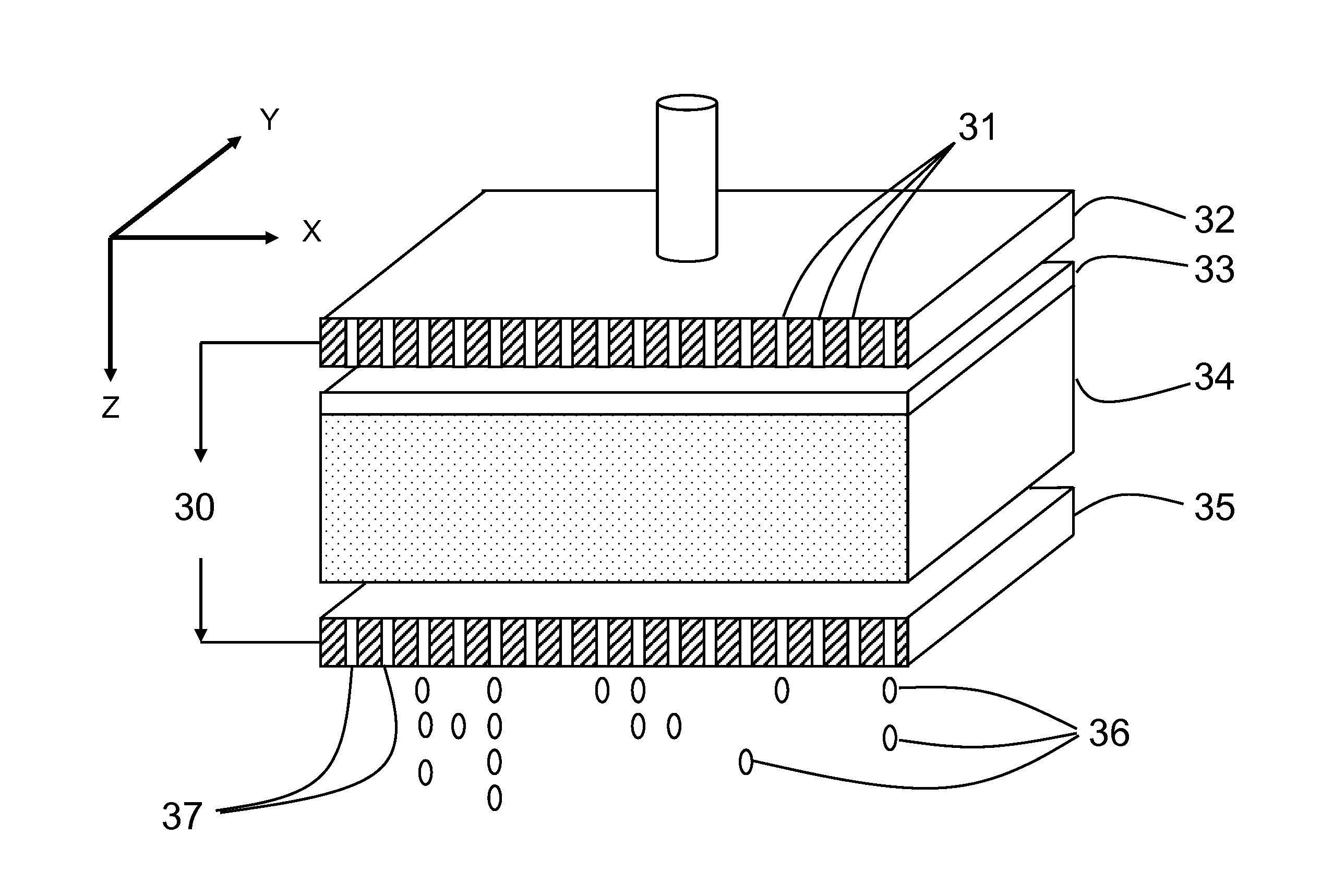
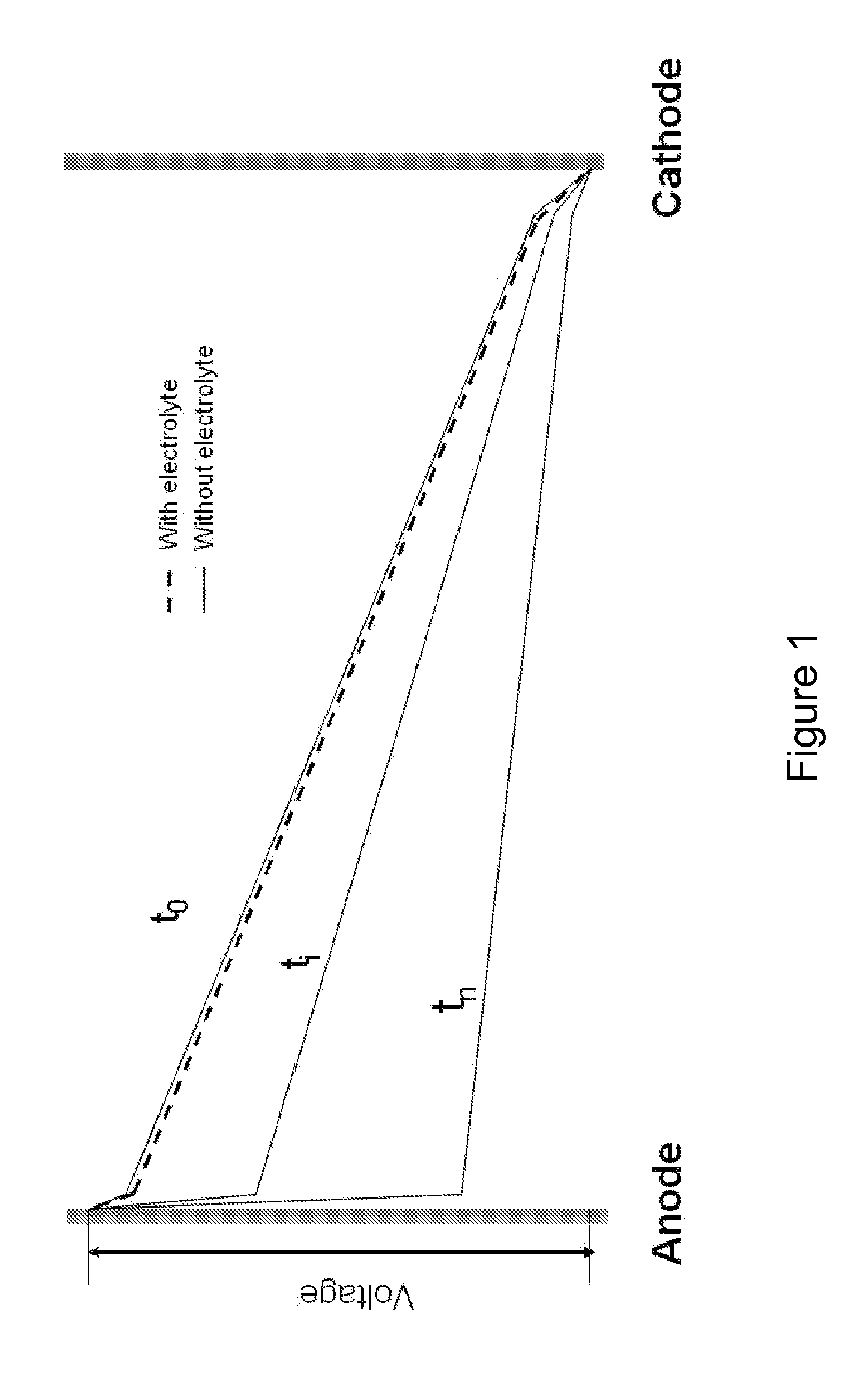
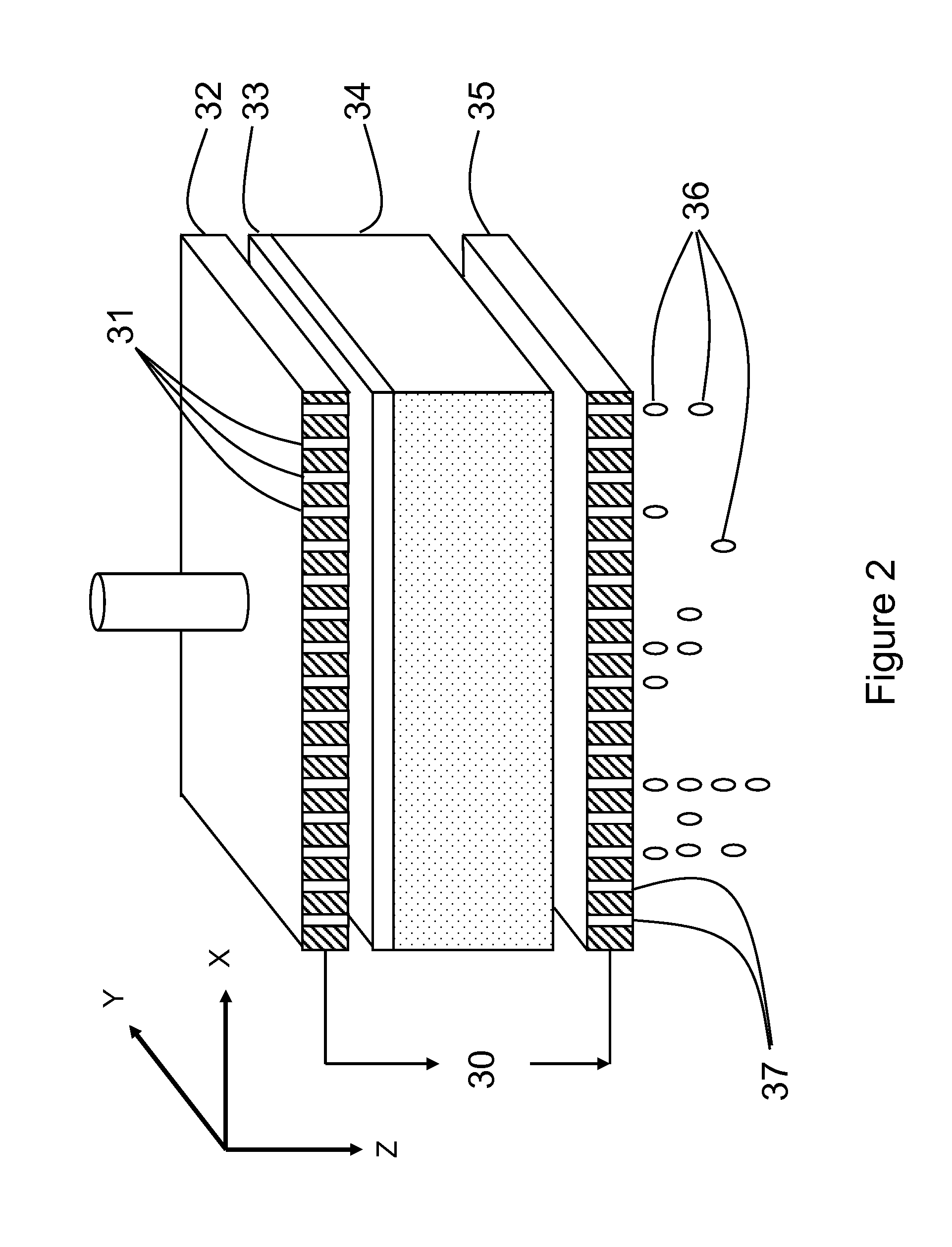
[0045]An electro-dewatering apparatus is known in the art and is more fully described in publication WO2007 / 143840. Referring now to the present application, FIG. 1 is a schematic representation of voltage as a function of distance between two electrodes for three time points without electrolyte (solid line) and with electrolyte (dashed line), highlighting the consequence of subjecting an electrolyte-poor substance to electro-dewatering. This image shows the drawbacks of the prior art whereby generating a current through a porous liquid-bearing substance rapidly leads to a decrease in voltage as a function of time and as a function of distance from the anode. The main reason that a zone of increased resistance appears near the anode is the outflow of cations away from the anode toward the cathode, thereby drawing water to the cathode and generating a crusty substance near the anode. This crusty substance has the property of severely limiting the amount of current that can flow throu...


PUM

PropertyMeasurementUnit
Fractionaaaaaaaaaa
Fractionaaaaaaaaaa
Fractionaaaaaaaaaa

Abstract

It is an object of the present invention to provide an improved method of electro-dewatering substances by increasing the efficiency with which water is removed from the substances, thus permitting substances to attain higher dryness levels with the same energy input and surface area, or to attain similar dryness levels with less energy input or less surface area. The method comprises placing the substance between at least two electrodes, at least one of which is adapted to allow fluid evacuation, depositing an electrolyte at the interface between the substance and one of the electrodes, wherein the two previous steps can be performed in any order, and, before impregnation of the electrolyte into the substance can occur, submitting the substance to a combination of pressure and electrical current so as to remove liquid from the substance; wherein the electrolyte should be added in sufficient quantity to substantially reduce or prevent the voltage drop that occurs near the at least one electrode and in sufficient volume to allow dispersion over the entire surface of the substance.

Description

TECHNICAL FIELD[0001]The present invention relates to the field of electro-dewatering and in particular, to new methods and apparatuses for increasing the efficiency of electro-dewatering.BACKGROUND[0002]Sludge is the semi-liquid residual material left from wastewater treatment processes. Sludge is highly charged with organic materials and toxic products and it is therefore critical not to simply redirect the pollution that originally affected water to other media such as soil and air. As sludge volume increases with population and industrial activity growth, treating and disposing of sludge is a constant challenge for both public and privately-held wastewater treatment plants (WWTP). In a context of ever-tightening environmental regulations and budgets, WWTP operators need to find new and viable alternatives allowing for efficient and economical sludge disposal or reuse.[0003]In most situations involving the production of large amounts of sludge such as at municipal or industrial w...

Claims


Application Information

Patent Timeline
IPC IPC(8): C02F1/469C02F11/14C02F11/12
CPCC02F1/469C02F1/4698C02F2209/05C02F2209/001C02F11/12C02F11/15
Inventor DERMOUNE, ABDERRAHMANECHAMOUMI, MOSTAFASILVERWOOD, ALAINBITON, FREDERIC
Owner GL&V CANADA INC
Why Eureka
Try Eureka