Buoyant airbarge and spinnaker sail combinations for generating electric power from wind

a technology of wind power generation and buoyant airbarges, which is applied in the direction of electric generator control, machine/engine, greenhouse gas reduction, etc., can solve the problems of reducing the operating space of the rotating turbine blades, reducing the operating space of the set of turbine blades, and reducing the power generation efficiency of the wind power generation system, so as to reduce the pulling force and achieve greater operating control.

Inactive Publication Date: 2012-03-01
KELLY PATRICK D
View PDF8 Cites 45 Cited by
  • Summary
  • Abstract
  • Description
  • Claims
  • Application Information

AI Technical Summary

Benefits of technology

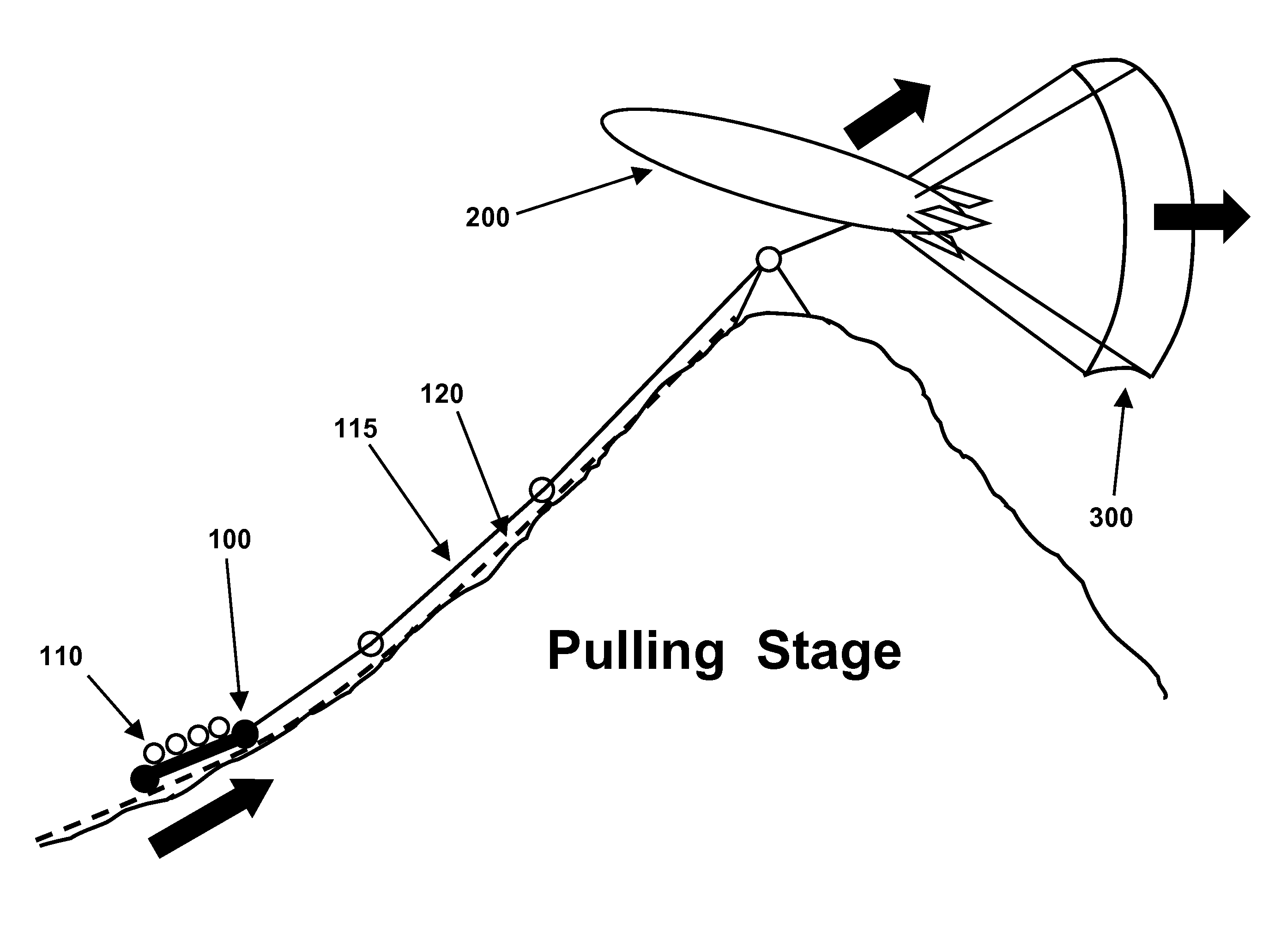
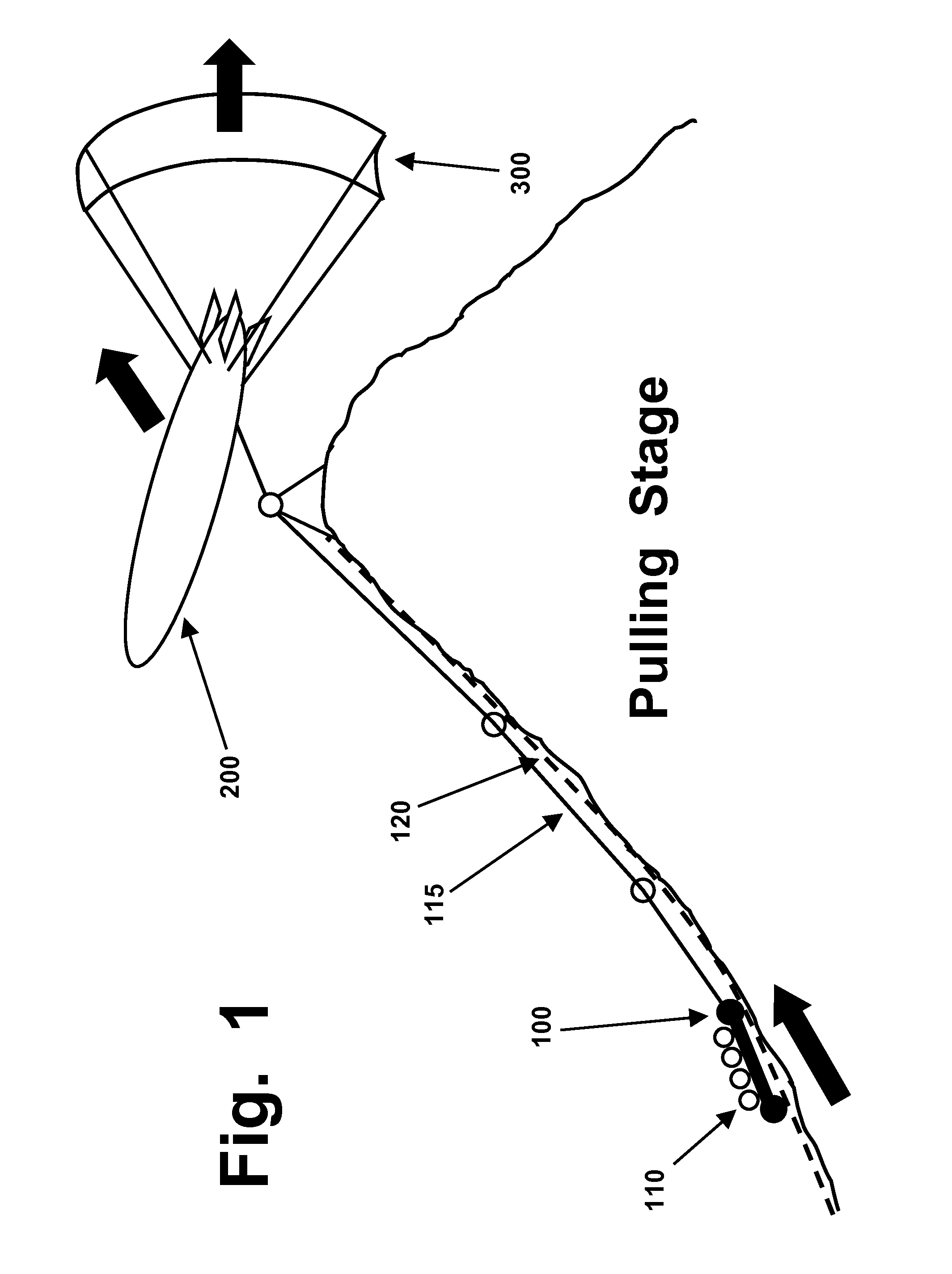
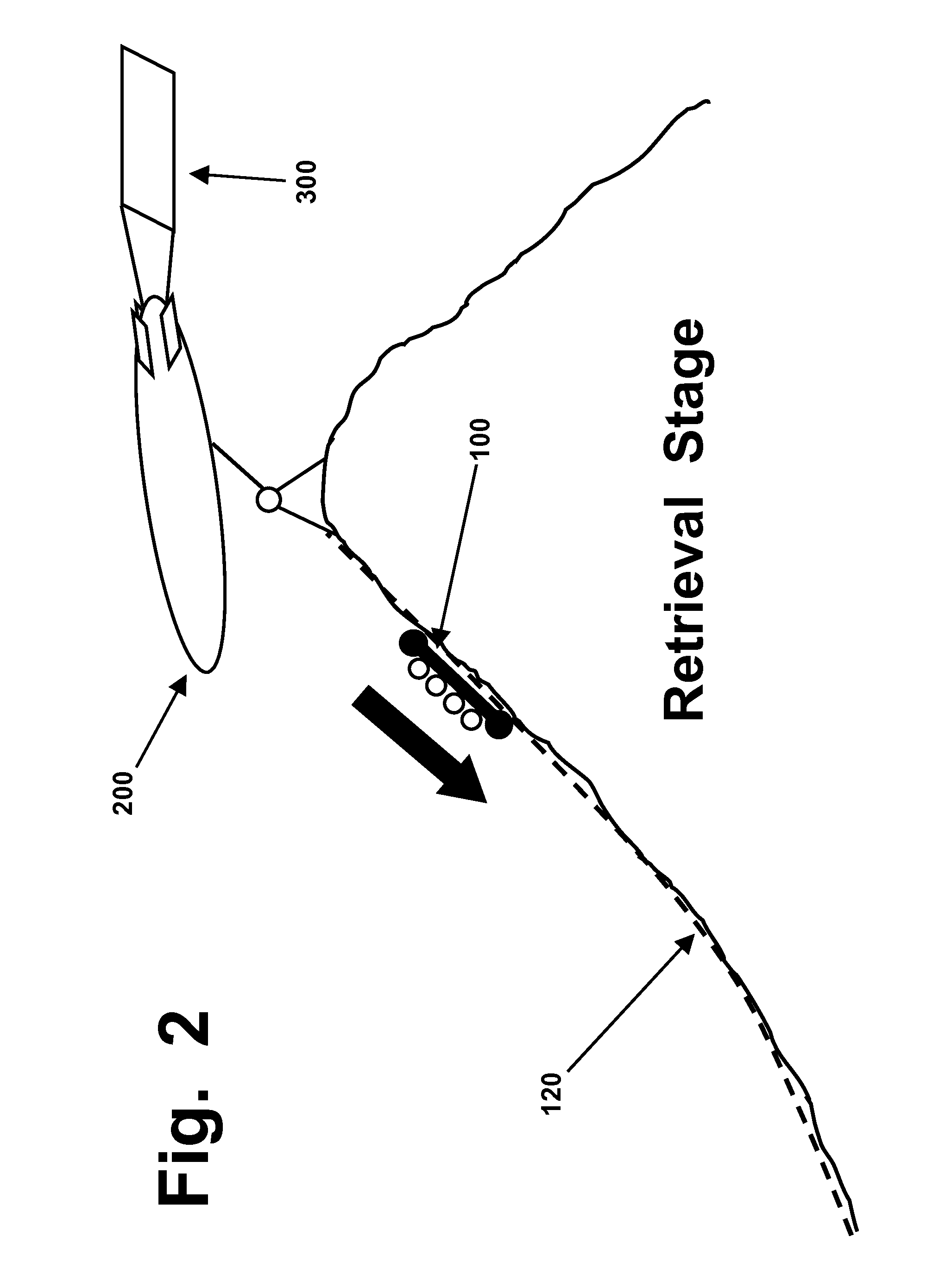
[0141]The spinnaker sail can function in a manner comparable to a horizontal parachute, with a rounded dome-like shape to provide it with stability. Its tethering system will enable at least one side of the sail to be released from tension, when the pulling stage of a power cycle has been completed and it is time to return the sail to a starting position, for the next power cycle. If a circular or polygonal sail is used, a powered hub unit in the center of the sail can be used to retract a set of radial reinforcing straps in the sail, in a manner which will temporarily shift the sail out of a domed configuration, and into a flattened planar configuration, so that it can be retrieved while flapping in the breeze like a flag, with minimal resistance and power requirements. Alternately, a spinnaker sail can shift into a “closed umbrella” configuration, pointing into the wind and with minimal projected area and wind resistance, if tension is kept on a center cable while any peripheral cables are relaxed.
[0145]In some preferred embodiments, the airbarge will travel away from its ground station, during each pulling cycle, while the spinnaker sail will effectively “tow” the airbarge in a downwind direction. This arrangement can allow a well-designed airbarge to act in conjunction with the spinnaker sail, to generate greater pulling power, and greater power output for the system.
[0148](ii) be coupled directly from the spinnaker sail to the electric power generators, which will slightly decrease the pulling force and power output, but which will provide the operators of the system with greater operating control, and with additional shutdown and stowage options if a storm is approaching or an accident occurs.

Problems solved by technology

The first glaring limitation of wind turbines becomes obvious from a simple glance at FIG. 3, or at any picture of any conventional wind turbine.
A set of rotating turbine blades requires that much room to operate, and nothing else can be positioned in, around, or near that “swept area”.
The “inefficiency factor” which requires attention at this point arises from the fact that the three blades of any conventional wind turbine occupy only about 5% of the swept area.
That 90-degree misalignment seriously hinders the efficient capture of wind power, by wind turbines; and, that misalignment problem acts along with the “95 percent empty space” factor in a cumulative and additive (rather than offsetting or compensating) manner, which further reduces the efficiency of 3-blade wind turbines.
Both of those two problems are inherent and unavoidable in the design of conventional wind turbines, and they stand squarely and stubbornly in the path of any efforts to achieve better efficiency levels, when wind turbines are used to generate electric power.
That is a noble and useful task; however, a fan blade segment with a round cross-section will not and cannot generate any torque to help drive the turbine and generate output power, regardless of how much wind blows against it.
Therefore, a significant zone at the center of a wind turbine contributes no useful power output, and should be regarded as a “dead-weight overhead expense”.
The fourth problem which reduces the efficiency of wind turbines is referred to herein as “the low-torque middle” problem.
Similarly, if someone is trying to calculate where a car (or fan blade) will be, at some point in the future, it is not enough to know where the car (or fan blade) is located at some point in time, and that it is moving at 20, or 50, or 100 miles per hour.
Because the blades of a wind turbine act as levers, which are used to generate torque that will drive the rotation of a shaft, the inner portions of those turbine blades simply cannot generate more than a small fraction of the torque which is driving the rotation of the shaft.
For each and all of the reasons described above (which act cumulatively, and simultaneously, to decrease efficiency and output), wind turbines are limited to only a small percentage of the efficiencies that might be reached by other types of wind-capture devices.
Even though ropes made of natural fibers could be used as described herein, they will degrade much more rapidly, when used outdoors, than cables made of synthetic materials suited for outdoor use.
Any fabric made from woven or knitted fibers will inevitably have some degree of permeability, to air and wind; however, since “tight weaves” are used to make sailcloth, and since the types of fibers used to make sailcloth tend to be “fluffy” when seen under a microscope, in a manner which enables them to create nearly airtight seals between adjacent strands, permeability to air flow, in any conventional sailcloth material, is very low, and close to negligible.
Factors such as how much fabric was used to make the parachute, or how high its dome might extend when in use, will have no effect on its projected area, and little if any effect on whether it will be able to safely hold and land a person or cargo package having a certain weight.
However, the height of a parachute dome has essentially zero effect on how rapidly a person or item will descend, when hanging from that parachute.
However, narrow or rigid design parameters do not apply, when it comes to airborne spinnaker sails.
As used herein, the term “buoyant” is limited to airborne devices that contain a buoyant gas (i.e., hydrogen or helium).
An elongated and streamlined balloon, with external but non-moving fins and with nothing more than a tethering attachment coupled to its nose, would come closer to the definition of an “aircraft”, but it still would not qualify.
In addition, there are no clear and agreed-upon rules as to whether a blimp-type device could ever qualify as an “aircraft”, even if it is carrying tons of complex machinery, and even if it has plenty of flight-related machinery that can help it stay pointed in some desired direction, if it nevertheless is incapable of being flown independently, and must be kept tethered to a cable to prevent it from being blown away.
However, not all buoyant lifting devices need to be designed and operated as “machines” with multiple moving parts.
However, that is not the conventional aeronautic use of the term “airfoil”, which refers to the cross-sectional shape of a wing, since that cross-sectional shape is crucial to how an airplane wing will generate varying quantities of lift, when the plane is flying at a range of different speeds.
However, the Applicant is not aware of any kite system ever being actually used, at any site which generated enough electric power to justify a connection to an electric power grid run by a public utility.
In general, it is believed and asserted by the Applicant herein that “basic kites” which have not been expanded or incorporated into more complex lifting devices (such as gas-filled buoyant airbarges having certain kite-like features, as described herein) will never be well-suited for electric power generation, because of issues of controllability and reliability, under the ranges of wind conditions that are likely to be encountered.
In general, the types of exceptionally powerful lift which are generated by the metal-covered wings of a passenger jet (which must lift and carry a heavy cylindrical fuselage that contributes little or no lift, to the jet) cannot be reached, or even approached, by a buoyant blimp, zeppelin, or similar aircraft which has a skin made of a flexible fabric.
However, if a tail structure or enlarged fuselage is incorporated into a “flying wing” aircraft, it will begin to violate or at least veer away from the definition quoted above.
That type of motion is highly undesirable, because it can greatly reduce the speed and fuel efficiency of an aircraft, and can make the crew and any passengers motion-sick, and can impose unwanted and possibly dangerous and destructive forces on an airplane traveling at high speed.
However, since the classic definition of “flying wing” refers to a “tailless” aircraft, a flying wing which has been given a tail structure is no longer a true “flying wing”, and has become a hybridized aircraft.

Method used


Image

  • Buoyant airbarge and spinnaker sail combinations for generating electric power from wind
  • Buoyant airbarge and spinnaker sail combinations for generating electric power from wind
  • Buoyant airbarge and spinnaker sail combinations for generating electric power from wind

Examples


Embodiment Construction

[0173]As briefly summarized above, this application discloses devices and methods that are designed to generate electric power, by capturing (or harvesting, converting, or similar terms) wind energy. One such device disclosed herein is an airborne traveling assembly referred to herein as an “airbarge and sail” unit (or system, assembly, etc.). It uses an airbarge (i.e., a wide and flat lifting device which will be unmanned during normal use), which is buoyant (i.e., filled with enough hydrogen or helium to overcome the weight of both the airbarge and the sail, in a manner which generates a net buoyant force that causes both the airbarge and sail to remain airborne unless mechanical means are used to force a descent), and which is sized and shaped to generate both lifting and pulling force, when allowed to rise into the path of the wind in a “nose up” orientation. Because of certain factors described in the Background section and below, it also is referred to as a “KMW” (kite-manta-w...


PUM


Abstract

Systems for generating electric power from wind are disclosed, which use buoyant aircraft and spinnaker sails to generate very large pulling forces, which will be used to drive electric generators. The buoyant aircraft, referred to as “airbarges”, will have large, wide, and flat shapes which combine various traits of kites, manta rays, and “flying wing” aircraft. They can be flown “nose up” during the pulling stage of each power cycle, and “nose down” during retrieval. Spinnaker sails are comparable to horizontal parachutes, with tethering systems that will enable them to be pulled back to a starting location in a “luffing flag” or “closed umbrella” configuration. Because of various factors, spinnaker sails can generate much greater power output and operating efficiency than 3-blade wind turbines. “Webbing sails” made from interwoven straps also are disclosed, which can be used even in extremely high winds.

Description

RELATED APPLICATION[0001]This application is a continuation-in-part of U.S. utility application Ser. No. 12 / 390,503, filed on Feb. 23, 2009 and published on Aug. 26, 2010 as 2010 / 213718.BACKGROUND[0002]This invention is in the field of electromechanical systems, and relates to combinations of gas-filled buoyant devices, and spinnaker sails, to convert wind energy into electric power.[0003]This application contains disclosures and descriptions of various components that were previously described in the above-cited “parent” patent application Ser. No. 12 / 390,503. All teachings and disclosures set forth in that application are incorporated herein, as though fully set forth herein.[0004]The system described in the above-cited application is not prior art against this C-I-P application, since both applications share the same priority date. Nevertheless, it is convenient to treat that previously-disclosed system as a foundation or “baseline” of information, and then focus on the new and a...

Claims


Application Information

Patent Timeline
Patent Type & Authority Applications(United States)
IPC IPC(8): F03D9/00
CPCF03D5/04F03D5/06F03D9/021Y02E10/72F05B2240/922F05B2240/98Y02E10/70F05B2240/921Y02E70/30F03D9/11F03D9/16F03D9/25
Inventor KELLY, PATRICK D.
Owner KELLY PATRICK D
Why Eureka
Try Eureka