
Method of delivering a medical device across a plurality of valves

Inactive Publication Date: 2012-02-23
ABBOTT CARDIOVASCULAR
View PDF16 Cites 74 Cited by
  • Summary
  • Abstract
  • Description
  • Claims
  • Application Information

AI Technical Summary

Benefits of technology

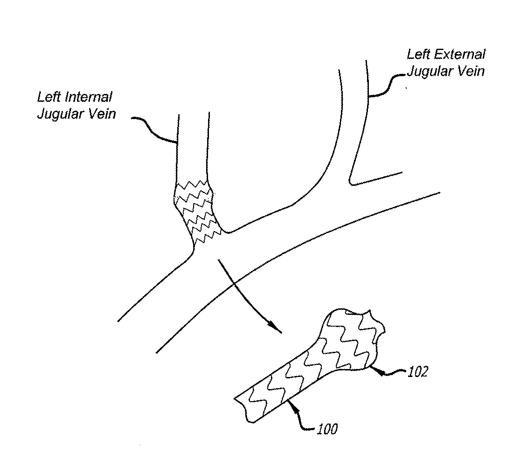
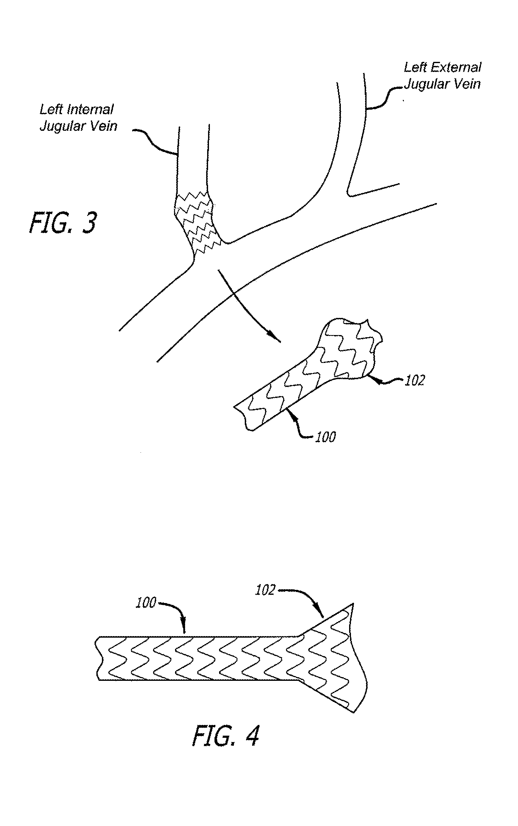
[0016]In some embodiments, the enlarged portion of the intraluminal scaffold includes a bistable construction. The enlarged portion, including the bistable construction, in the expanded condition can have a profile larger than a diameter of the cylindrical portion in the expanded condition. The enlarged portion also can have sufficient flexibility to conform to the distended portion of the vessel without plastic deformation.
[0041]In accordance with another aspect of the disclosed subject matter, a method of deploying a medical device is provided. The method includes: establishing an open condition of a valve in a vessel of a patient; moving a medical device through the opened valve; and deploying the medical device at a target site, wherein establishing the open condition, moving the medical device and deploying the medical device are completed without negatively impacting the function of the valve.
[0046]In accordance with another aspect of the disclosed subject matter, a method of deploying a medical device across a plurality of valves of a vessel of a patient is provided. A catheter is provided which has an inner shaft member and an outer shaft member co-axially disposed and axially moveable relative to each other. The catheter is positioned in a vessel having a plurality of valves including a first valve and a second valve. A distal end of the outer shaft member is advanced across the first valve without permanently impacting the function of the first valve; moving the inner shaft member axially relative to the outer shaft member; and advancing a distal end of the inner shaft member across the second valve without permanently impacting the function of the second valve.

Problems solved by technology

Multiple Sclerosis (MS) is a debilitating disease in which the myelin surrounding the nerves is damaged, resulting in inhibition of nerve communication and impairment of physical and cognitive abilities.
These abnormalities cause blood “refluxing”, or retrograde flow, which creates reflux in the central nervous system.
Poor venous drainage and the resulting deposition of iron may be a primary or secondary cause of other diseases as well.
First, the cost of manufacturing a non-cylindrical stent is substantially higher using traditional processes, and second, there has not been a strong demand for non-cylindrical stents since most diseased vessels are essentially cylindrical, and any anatomical deviations can be compensated for through balloon deployment and touch-up.
However, there are no stents available on the market that are sized or designed for treating the vessel conditions relevant to CCSVI and the use of cylindrical stents to do so may not be fruitful.
First, such stents have a tendency to dislodge from the vein because the veins have low radial force and are relatively large compared to typical stent diameters.
When this happens, the stent may flow downstream and cause risk to the patient if it enters the heart, another organ, or otherwise disrupts blood flow, for example.
Second, a stent with a cylindrical profile may not conform fully to a bulbous vein, and there may therefore be poor scaffolding and opportunity for thrombus formation in the gaps between the vein wall and the stent.
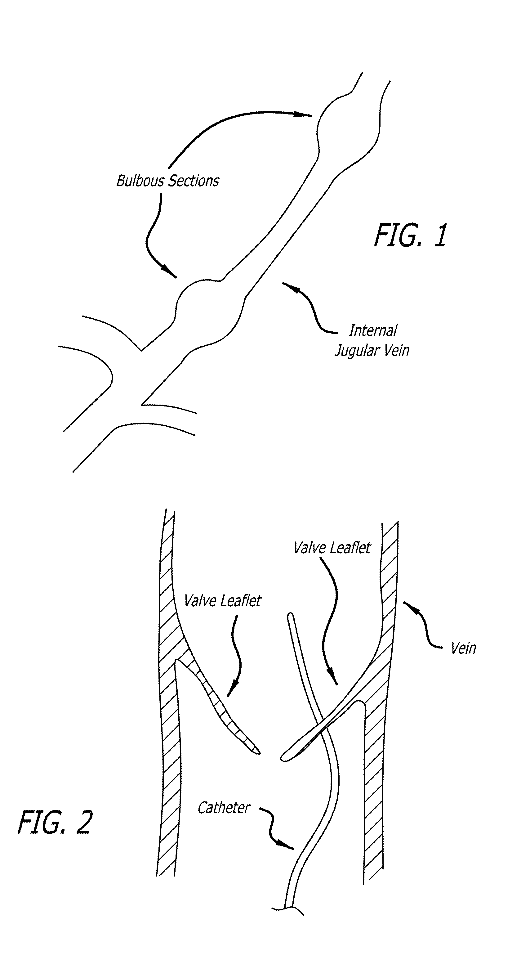
However, as shown in FIG. 2, even basic access to a jugular can be difficult to accomplish without damaging the venous valves.
Therefore, as the guidewire is passed into the vein, it may tend to catch the valve leaflets and press against them in a resistive manner.
Due to the relative weakness of the leaflets, they may tear or be otherwise damages.
If the leaflets tear, they may be unable to resist backflow and therefore their function will be destroyed.
This same problem can occur when other devices, such as balloon catheters or other catheter devices, are passed in the same direction as the guidewire.

Method used


Image

  • Method of delivering a medical device across a plurality of valves
  • Method of delivering a medical device across a plurality of valves
  • Method of delivering a medical device across a plurality of valves

Examples


Embodiment Construction

[0067]While the disclosed subject matter may be embodied in many different forms, reference will now be made in detail to specific embodiments of the disclosed subject, examples of which are illustrated in the accompanying drawings. This description is an exemplification of the principles of the disclosed subject matter and is not intended to limit the subject matter to the particular embodiments illustrated.

[0068]In accordance with one aspect of the disclosed matter, an intraluminal scaffold is provided which is suitable to be implanted in a body lumen, such as a blood vessel or the like, e.g., a vein, of a patient. In general, the construction of the intraluminal scaffold can be selected such that the scaffold, or a portion thereof, can either support or conform to a body lumen. By “conforming,” when the term relates to a scaffold of a portion thereof, it is intended that the overall geometry and stiffness of the scaffold, or relevant portion thereof, are such that the scaffold (o...


PUM


Abstract

Devices and methods for treating veins and venous conditions, such as chronic cerebrospinal venous insufficiency, are provided. In one aspect, the disclosed subject matter provides an intraluminal scaffold having a generally tubular body with a lumen defined therethrough, the tubular body having a compressed condition for delivery and an expanded condition for implant within a vessel having a distended portion, at least a length of the tubular body configured to form an enlarged portion in the expanded condition to engage a wall of the distended portion of the vessel. Methods for fabricating and using the scaffold, methods for remodeling a vein, and methods of deploying a medical device in a vessel without negatively impacting the function of a valve of the vessel, are also provided.

Description

CROSS REFERENCES TO RELATED APPLICATIONS[0001]The present application claims priority from U.S. Provisional Application Ser. No. 61 / 324,031, filed Apr. 14, 2010, which is incorporated by reference in its entirety.BACKGROUND[0002]1. Technical Field[0003]This disclosed subject matter generally relates to devices and methods for treating veins and conditions related to veins. More particularly, the disclosed subject matter relates to devices and methods that are useful for treating venous anatomies to improve venous sufficiency.[0004]2. Description of Background[0005]Multiple Sclerosis (MS) is a debilitating disease in which the myelin surrounding the nerves is damaged, resulting in inhibition of nerve communication and impairment of physical and cognitive abilities. There is currently no cure for MS, but management of the disease has been advanced through the use of medical treatments, diet, and other non-surgical means. These treatments reflect the lack of a known cause of MS. MS suf...

Claims


Application Information

Patent Timeline
IPC IPC(8): A61F2/24A61F2/82
CPCA61F2/2475A61F2/88A61F2/915A61F2/958A61F2002/825A61F2002/8483A61F2230/0078A61F2002/91566A61F2220/005A61F2220/0058A61F2220/0075A61F2230/0054A61F2230/0076A61F2002/91558
Inventor VON OEPEN, RANDOLFEHRENREICH, KEVIN J.MCCRYSTLE, KELLY J.
Owner ABBOTT CARDIOVASCULAR
Learn More