
Methods and devices for spinal fusion

a spinal fusion and fusion device technology, applied in the field of bone fusion devices, can solve the problems of compromising implant strength, unable to increase the size, loosening and failing of the pedicle screw after installation, etc., and achieve the effect of improving implantation strength and stiffness

Inactive Publication Date: 2012-02-23
DOCTORS RES GROUP
View PDF4 Cites 17 Cited by
  • Summary
  • Abstract
  • Description
  • Claims
  • Application Information

AI Technical Summary

Benefits of technology

[0010]According to the present invention, a pedicle fastener for implantation during a spinal fusion procedure includes a head and shank. The shank is connectable to the head and extends outwardly therefrom. The shank may include a shielding feature formed therein for accommodating an adhesive augmenting the pedicle fastener for improving implantation strength and stiffness thereof. The adhesive may be a biocompatible polymeric material and, preferably, is biocompatible polyurethane. In some embodiments, the adhesive and the pedicle fastener may be provided together as a spinal fusion kit.
[0013]According to the present invention, the pedicle fastener may include a heating feature for applying a heat source to the pedicle fastener to accelerate polymerization. In some embodiments, the heating feature may be the longitudinal cannula, which may accept a heating element therein for accelerating polymerization of the adhesive. In other embodiments, the heating feature may include a removable extension extending from the head of the pedicle fastener. In some embodiments, the pedicle fastener may be provided with frozen adhesive provided thereon such that the frozen adhesive thaws and polymerizes after implantation. In some embodiments, the frozen adhesive may thaw and polymerize due to natural body heat, while in other embodiments, polymerization of the frozen adhesive may advantageously be accelerated using the heating features discussed above.

Problems solved by technology

However, in some patient populations, the pedicle screws loosen and fail after installation, particularly for patients with osteoporosis or where the pedicle screw was installed to replace a previously failed pedicle screw that already stripped the screw hole.
However, in many instances, the size and / or shape of the patient's pedicle may limit the size of the pedicle screw, thereby making it impossible to increase the size thereof.
However, these geometric features may compromise implant strength and may be difficult to revise in the future, if necessary.
However, the stiffness of PMMA does not match that of the surrounding bone, which can lead to additional stress at the screw purchase.
Additionally, the time before the PMMA sets, during which it may be implanted and / or worked, is relatively small, providing a surgeon with a very limited window in which the augmented pedicle screw must be inserted.
In the event of a screw purchase failure or implantation error, PMMA is also difficult to rework, due to its rigidity and brittleness.
Additionally, PMMA is not inherently adhesive to either bone or metal and, therefore, may not form a long lasting bone-PMMA or PMMA-screw interface.
The act of screwing the pedicle screw into the patient's bone may also scrape the PMMA off of the threads of the pedicle screw, thereby further compromising the screw purchase.
However, mineral cements have low tensile strength and may resorb before adequate bone ingrowth is achieved around the pedicle screw.
Additionally, mineral cement, like PMMA, is not inherently adhesive to either bone or metal and, therefore, may not form a long lasting interface.

Method used


Image

  • Methods and devices for spinal fusion
  • Methods and devices for spinal fusion
  • Methods and devices for spinal fusion

Examples


Embodiment Construction

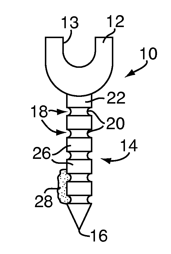
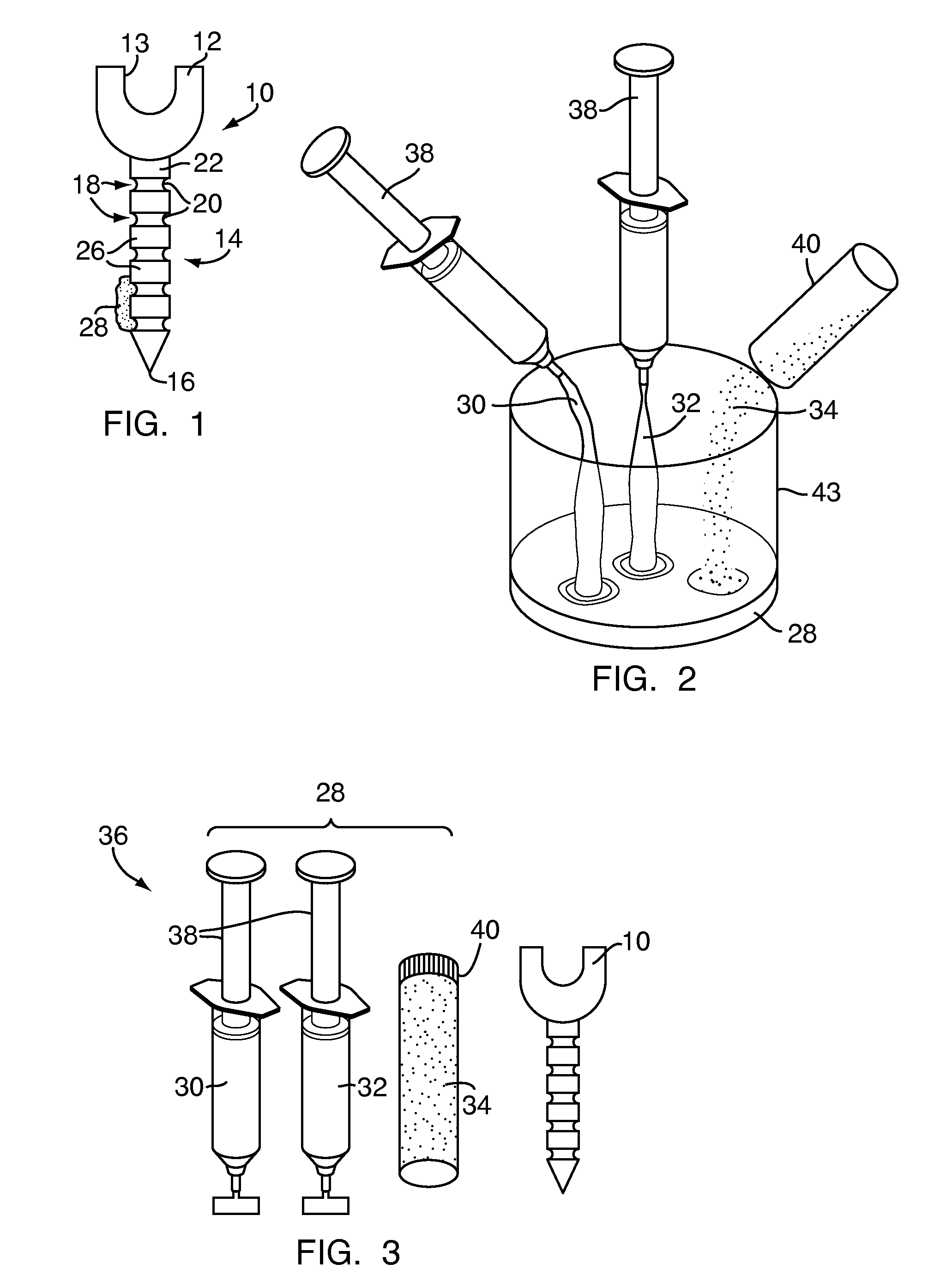
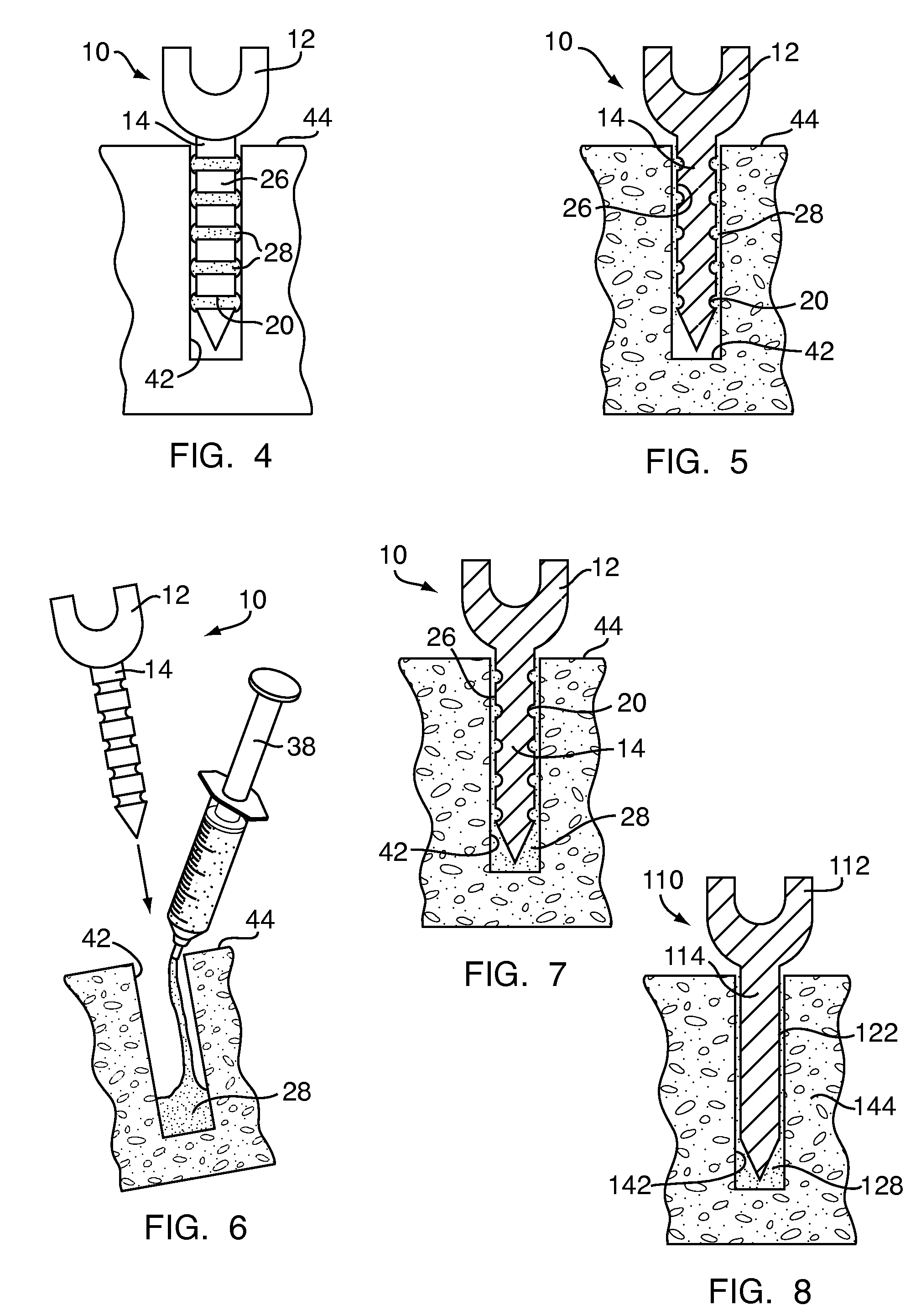
[0041]Referring to FIG. 1, a pedicle fastener 10 includes a head 12 and a shank 14 extending outwardly from the head 12 to a shank tip 16. The head 12 may be similar to known pedicle screw heads, including at least one suitable connection feature 13 for rods, plates or the like. The shank 14 has at least one shielding feature 18 formed therein. For example, the shielding features 18 may be a plurality of annular grooves 20 formed in an outer surface 22 of the shank 14 and extending around a circumference thereof. The annular grooves 20 are separated by ridges 26 also extending around the circumference of the shank 14. In some embodiments, the annular grooves 20 and the ridges 26 may include smooth transitions therebetween, providing the outer surface 22 with an undulating sinusoidal-type profile.

[0042]Although shown as a single unit, in some embodiments, the pedicle fastener 10 may be part of a spinal fusion device (not shown) including the pedicle fastener 10, a rod (not shown) and...


PUM


Abstract

A pedicle fastener for implantation during a spinal fusion procedure includes a head and shank, the shank being connectable to the head and extending outwardly therefrom. The shank may include a shielding feature formed therein for accommodating an adhesive augmenting the pedicle fastener and improving implantation strength and stiffness thereof. A method for implanting the pedicle fastener includes forming a hole in a pedicle, applying the adhesive to the hole and sliding the shank of the pedicle fastener into the hole. The adhesive may also be applied to the hole through direct injection, injection through a longitudinal cannula formed in the pedicle fastener or by depositing the adhesive on the shank and inserting the shank into the hole. Polymerization of the adhesive may be accelerated by heating the pedicle fastener.

Description

FIELD OF THE INVENTION[0001]The present invention relates to methods and devices for use in spinal fusion and, more particularly, to bone fasteners and methods of implantation thereof.BACKGROUND OF THE INVENTION[0002]There are many situations in which bones or bone fragments are fused, including fractures, joint degeneration, abnormal bone growth, infection and the like. For example, circumstances requiring spinal fusion include degenerative disc disease, spinal disc herniation, discogenic pain, spinal tumors, vertebral fractures, scoliosis, kyphosis, spondylolisthesis, spondylosis, Posterior Rami Syndrome, other degenerative spinal diseases, and other conditions that result in instability of the spine. In many situations, bone screws are used in orthopedic surgery to stabilize the bones or to affix stabilizing equipment thereto.[0003]For instance, during spinal fusion, pedicle screws are often implanted to correct, or to aid in correcting, the spinal instability. For example, pedic...

Claims


Application Information

Patent Timeline
Patent Type & Authority Applications(United States)
IPC IPC(8): A61B17/86
CPCA61B17/7032A61B17/7098A61B17/8836A61B17/864A61B17/8808A61B17/8625
Inventor KOLB, ERICAKKARAPAKA, NARESHBOXBERGER, JOHNTOMICH, JOHN
Owner DOCTORS RES GROUP
Learn More