
Dynamic and depolarized dynamic light scattering colloid analyzer

a dynamic light scattering and analyzer technology, applied in the field of optical measurement and characterization, can solve the problems of unsatisfactory solutions to accurately measure in both these regimes, the decay rate of depolarized time correlation functions is often many times more rapid than that of dls, and the inability to use ddls as a popular measurement method, etc., to achieve the extension of ddls, improve the accuracy and the application range of dls, and improve the accuracy of extremely low volum

Active Publication Date: 2012-02-23
SCATTERING SOLUTIONS
View PDF1 Cites 30 Cited by
  • Summary
  • Abstract
  • Description
  • Claims
  • Application Information

AI Technical Summary

Benefits of technology

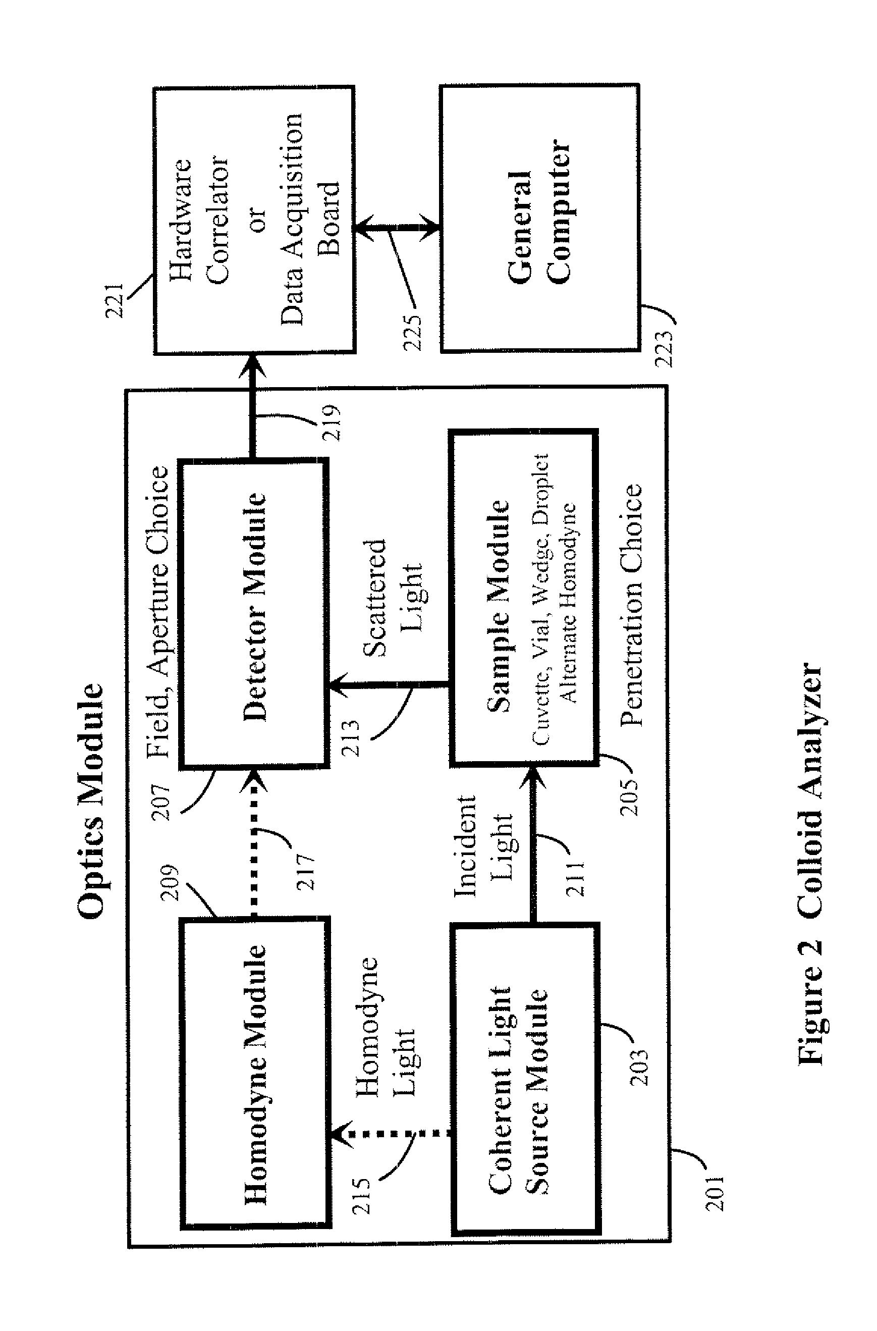
[0006]The present invention introduces techniques and alignment procedures applicable to an apparatus for the extension of Dynamic Light Scattering (DLS) and Depolarized Dynamic Light Scattering (DDLS) for characterizing (e.g., determining particle size, size distribution, and / or particle aspect ratio) colloidal suspensions of particles into concentration regions where conventional measurements are currently difficult or impractical. The first region includes concentrated turbid suspensions that frequently appear visually opaque, and where excessive multiple scattering typically may give a falsely low estimate of particle size. The second region is the opposite extreme where insufficient signal is available to determine the rotational or even the translational relaxation time of the particles, typically when particles are too small, too few, have insufficient refractive index difference from the suspending liquid, or where only the depolarized component is of interest. Separately or in combination, aspects of this invention improve both accuracy and the application range of DLS, and also extend DDLS to formerly inaccessible regions. The invention and its subsidiary aspects described below enable an effective apparatus to be implemented more simply than many others, allowing such possible configurations as a remote probe for process control in hostile environments, accurate characterization of extremely low volumes of specimen, measurement of specimens presented as a droplet on a transparent flat surface, or contained within circular vials or other shaped cuvettes or capillaries, with improvements of accuracy of measurement of particle hydrodynamic radius, polydispersity, and deviations from sphericity, together with prediction of expected error boundaries, and other desirable advantages. While many DLS and DDLS instruments require digital single photon detection with either photomultipliers or expensive avalanche photodiodes (APD) to achieve their performance, here we offer methods of using analog detection with conventional APD or silicon diode photodetector operation to obtain excellent measurements.

Problems solved by technology

To date, technical solutions to measure accurately in both these regimes remain unsatisfactory.
DDLS has not yet become a popular method for measurement because depolarized signals are typically weak and therefore often obscured by interfering signals such as stray light, optical imperfections, or other system noise sources.
In addition, depolarized time correlation functions often decay many times more rapidly than those of DLS, especially for small particles.
Increased frequency and reduced signal both present challenges for typical detectors and their following electronics.
Typical photodetectors optimized for weak signals, e.g., photomultiplier tubes, also suffer from dead time, after-pulsing and noise problems that arise from detecting a small number of photons per correlation time of the relaxation process.

Method used


Image

  • Dynamic and depolarized dynamic light scattering colloid analyzer
  • Dynamic and depolarized dynamic light scattering colloid analyzer
  • Dynamic and depolarized dynamic light scattering colloid analyzer

Examples


Embodiment Construction

[0021]To maximize the measurable range of particle and particle suspension characteristics, such as particle radius, aspect ratio, and concentration, under a variety of empirical constraints, several optical arrangements are presented. The applicable ranges of these arrangements are sketched in FIG. 1, which is a diagram based upon numerical predictions and approximate empirical verification of regions of performance capabilities accessible with the present invention. The abscissa covers a range of fractional volume concentration of particles suspended in a liquid, from 1 part in 108 up to levels limited by the maximum feasible packing fraction. The ordinate covers a range of particle radii from 1 nm to 10 microns, rather larger than the conventionally accepted and typically more limited range of DLS. This exemplary figure is calculated and drawn for near-backscatter conditions (nominally 168°), for a particle-liquid differential refractive index of about 1.2 (polystyrene latex sphe...


PUM


Abstract

Apparatus are described for measuring the characteristics of colloidal particles suspended in transparent media by Dynamic Light Scattering (DLS) and Depolarized Dynamic Light Scattering (DDLS) into regions where conventional measurements are difficult or impractical. Matching the diameter of an illuminating beam and an intersecting diameter of a field stop image extends measurements into regions that include concentrated turbid suspensions that frequently appear so visually opaque that multiple scattering typically gives a falsely low estimate of particle size. At the opposite extreme, where insufficient signal is available to determine either or both of the translational and / or rotational relaxation times of the particles, typically where they are too small, too few, or of insufficient refractive index difference from the medium to scatter enough light, measurements can be improved by: a) using a sufficiently large aperture such that many coherence areas fall upon the detector; and b) optical homodyne amplification of the scattered signal.

Description

BACKGROUND OF THE INVENTION[0001]The present invention relates to the field of optical measurement and characterization of a variety of types of particles suspended in a fluid. In particular, methods and apparatus are described for extending conventional boundaries of particle hydrodynamic radius measurement to both higher and lower particle concentration, and further for extending depolarized dynamic light scattering capabilities used for shape assessment.[0002]Dynamic Light Scattering (DLS) is used extensively in research laboratories and elsewhere for the development of new materials and processes, and less commonly is used for process monitoring and control. Commercial applications exist in several industries, including but not limited to: pharmaceuticals (small molecules and protein therapeutics), medical diagnostics (histology, bodily fluids, cataracts), consumer products (personal care, cosmetics, paints, detergents), chemicals, environmental monitoring and remediation (parti...

Claims


Application Information

Patent Timeline
IPC IPC(8): G01N15/02G01N21/01
CPCG01N15/0211G01N21/49G01N21/51G01N2015/1093G01N15/10G01N2015/1087G01N2015/0222G01N15/1434G01N2201/06113G01N2015/103G01N2015/1029
Inventor SMART, ANTHONY EMEYER, WILLIAM V.SALTIEL, CRAIG J.
Owner SCATTERING SOLUTIONS
Learn More