Satellite signal tracking method and receiver

Active Publication Date: 2012-02-16
SEIKO EPSON CORP
View PDF15 Cites 20 Cited by
  • Summary
  • Abstract
  • Description
  • Claims
  • Application Information

AI Technical Summary

Benefits of technology

[0009]An advantage of some aspects of the invention is to provide a novel technique of appropriately acquiring the satellite signal.
[0013]Unlike a simple technique in which the satellite signal is acquired using the first Doppler frequency computed using the received signal of the satellite signal, the satellite signal is acquired using the second Doppler frequency computed using the first Doppler frequency and the signal from the sensor unit including at least the acceleration sensor. As a result, it is possible to appropriately acquire the satellite signal using the second Doppler frequency having higher accuracy than that of the first Doppler frequency.
[0015]According to the second aspect, it is possible to obtain the position with higher accuracy by correcting the position computed using the signal from the sensor unit using the provisional position computed using the first Doppler frequency. In addition, since the viewing direction to the positioning satellite is appropriately obtained using the accurate position, it is possible to improve accuracy of the computed second Doppler frequency.
[0021]According to the fifth aspect, since the weight factor of the third Doppler frequency is larger than that of the first Doppler frequency in the synthesizing, it is possible to compute the second Doppler frequency by giving a higher weight to the third Doppler frequency.
[0024]Since filtering via the second loop filter is performed using a loop bandwidth narrower than that of the first loop filter, it is possible to improve Doppler frequency computation accuracy. In addition, since the result of filtering via the second loop filter and the second Doppler frequency are used, it is possible to obtain the fourth Doppler frequency with higher accuracy than that of the first Doppler frequency. Since the fourth Doppler frequency is used, it is possible to more reliably carry out the satellite signal tracking.
[0026]According to the seventh aspect, the satellite signal is acquired using the first Doppler frequency when the satellite signal satisfies the high-strength condition. In contrast, the satellite signal is acquired using the second Doppler frequency when the satellite signal does not satisfy the high-strength condition. As a result, it is possible to reduce a processing load relating to the satellite signal tracking.

Problems solved by technology

In a case where the positioning system using the satellite signal is solely used, the position computation accuracy is degraded due to various error sources.
If the detection accuracy of the acceleration sensor is low, a velocity necessary to compute the Doppler frequency may not be correctly obtained.
If the accuracy of the position computation is low, a viewing direction necessary to compute the Doppler frequency may not be correctly obtained.
While an MEMS sensor has some advantages such as a small size, a light weight, inexpensive cost, and low power consumption, it has disadvantages in that it is vulnerable to influence from the external environment such as impact, vibration, or temperature change.
For this reason, a significant error may be included in the detection result of the acceleration sensor due to the influence from the external environment such as temperature change or vibration.
In addition, the accuracy of the position computation may also be significantly degraded due to various reasons including the environment for receiving the satellite signal, such as a multipath environment or a weak electric field environment, a received signal strength, and arrangement of the positioning satellites.

Method used


Image

  • Satellite signal tracking method and receiver
  • Satellite signal tracking method and receiver
  • Satellite signal tracking method and receiver

Examples


first example

2-1. First Example

[0125]In the first example, the first position computation system 1 described in conjunction with “1-1 First Position Computation Method” is applied to a car navigation apparatus 1000.

2-1-1. Data Structure

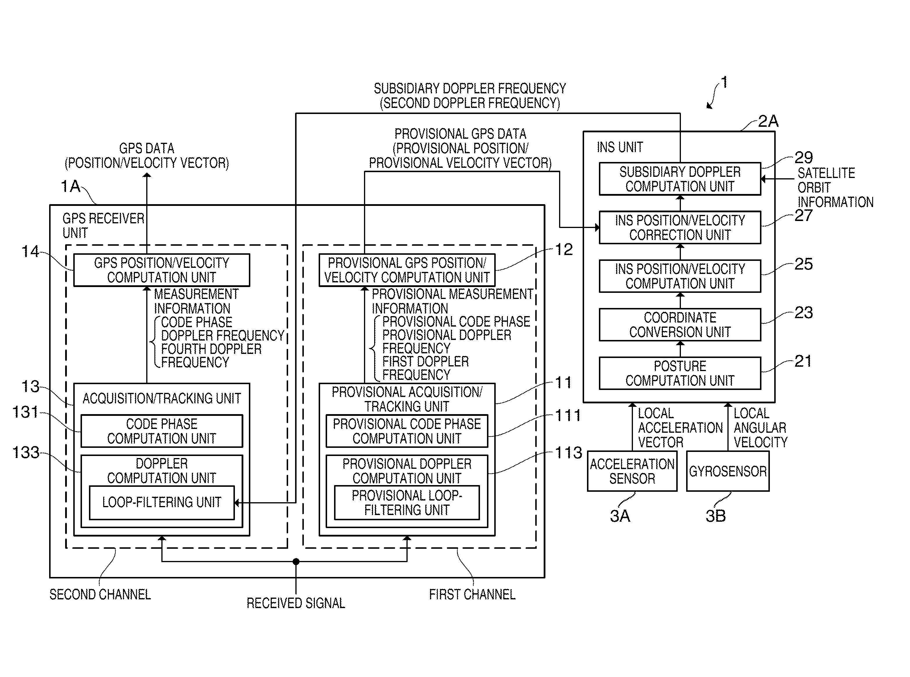
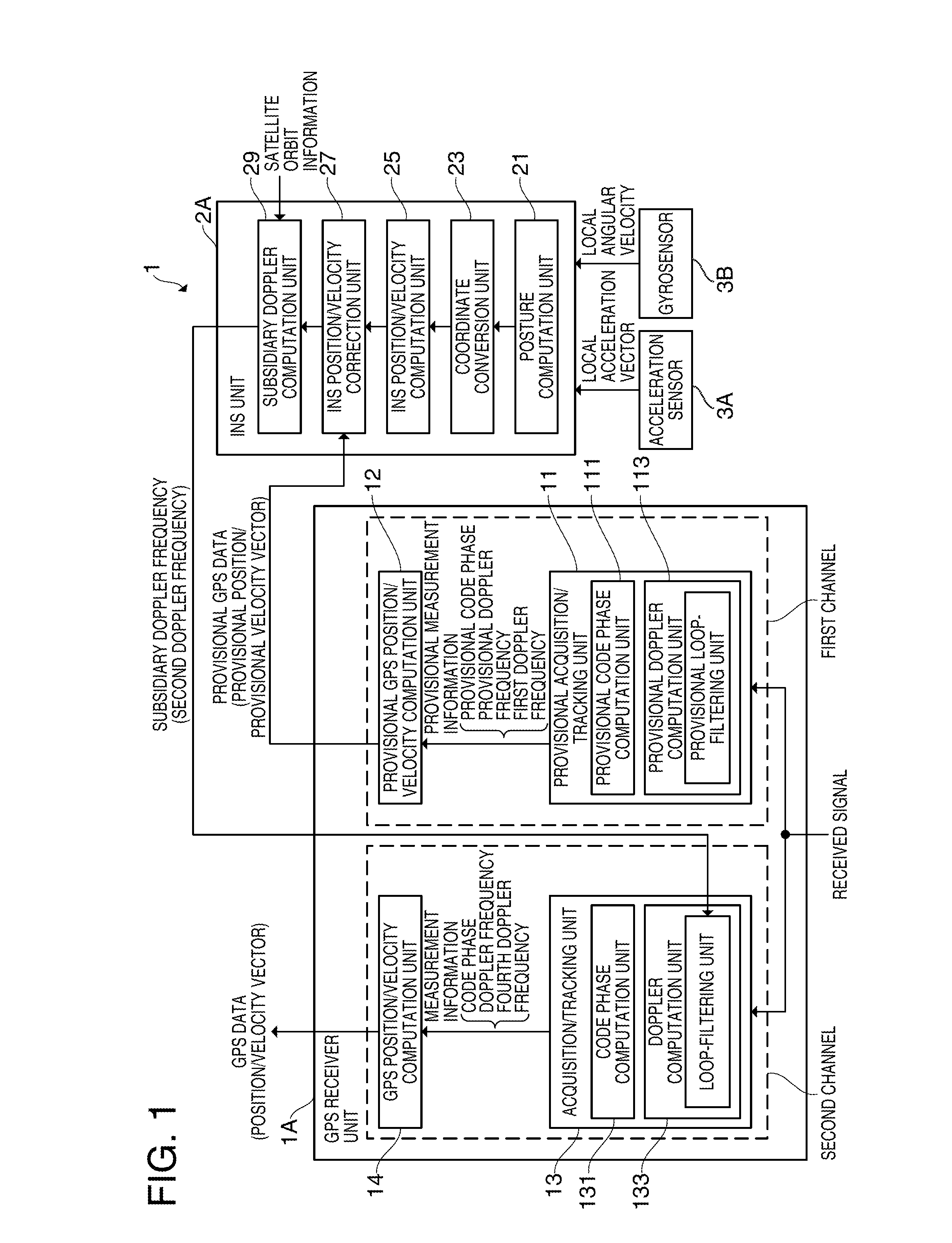
[0126]As shown in FIG. 4, the storage unit 160 of the baseband processing circuit unit 120 of the first example stores the first baseband processing program 161 read by the processing unit 150 and executed in the first baseband process (refer to FIG. 9) as a program. The first baseband processing program 161 includes a provisional acquisition / tracking program 1611, an acquisition / tracking program 1613, a provisional GPS position / velocity computation program 1615, and a GPS position / velocity computation program 1617 as a subroutine.

[0127]In the first baseband process, the processing unit 150 carries out two kinds of processes including a provisional acquisition / tracking process and an acquisition / tracking process for each tracking target satellite and computes and ...

second example

2-2. Second Example

[0154]The second example is an example for applying the second position computation system 2 described in “1-2. Second Position Computation Method” to a car navigation apparatus 1000. In the second example, like reference numerals denote like functional configurations, data structures, process steps as in the first example, and description thereof will be omitted.

2-2-1. Data Structure

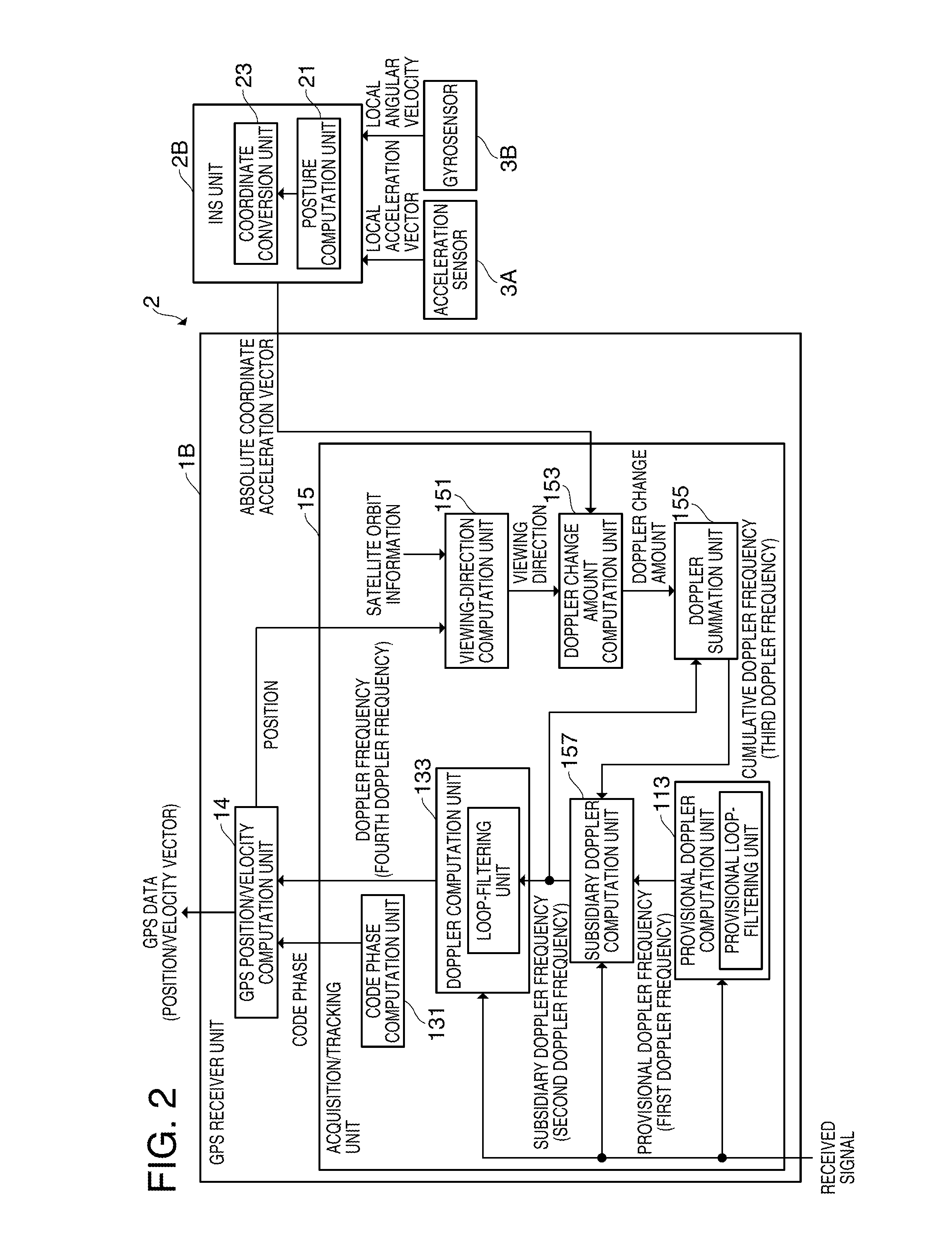
[0155]FIG. 11 is a diagram illustrating an exemplary data structure of the storage unit 160 of the baseband processing circuit unit 120 according to the second example. The storage unit 160 stores a second baseband processing program 162 executed in the second baseband process (refer to FIG. 14) as a program. The second baseband processing program 162 includes, as a subroutine, a provisional acquisition / tracking program 1611, an acquisition / tracking program 1613, a GPS position / velocity computation program 1617, and a subsidiary Doppler computation program 1621.

[0156]In addition, the ...


PUM


Abstract

A satellite signal tracking method performed by a receiver that receives a satellite signal from a positioning satellite, the satellite signal tracking method including: computing a first Doppler frequency using a received signal obtained by receiving the satellite signal, computing a second Doppler frequency using the first Doppler frequency and a signal from the sensor unit including at least an acceleration sensor, and acquiring the satellite signal using the second Doppler frequency.

Description

BACKGROUND[0001]1. Technical Field[0002]The present invention relates to a satellite signal tracking method and a receiver.[0003]2. Related Art[0004]As a positioning system using a satellite signal, there is known a global positioning system (GPS), which is used in a position computing apparatus integrated in a mobile phone, a car navigation apparatus, or the like. In the GPS, a position computation is performed in which position coordinates of the position computing apparatus and a time-watch error are obtained based on information such as positions of a plurality of GPS satellites or pseudo distances from each GPS satellite to the position computing apparatus.[0005]In a case where the positioning system using the satellite signal is solely used, the position computation accuracy is degraded due to various error sources. For this reason, various techniques have been proposed to improve the position computation accuracy. For example, in regard to a flying object having an accelerome...

Claims


Application Information

Patent Timeline
IPC IPC(8): G01S19/40G01S19/24
CPCG01S19/26G01S19/29G01S19/254
Inventor MIZUOCHI, SHUNICHIMATSUMOTO, KAZUMIKUMAR, ANAND
Owner SEIKO EPSON CORP
Why Eureka
Try Eureka