Oscillating immunoassay method and device
an immunoassay and immunoassay technology, applied in the field of immunoassay methods and devices, can solve the problems of delayed patient receipt, increased analysis cost, and detrimental to patient condition or prognosis, and achieve the effect of reducing the cost of laboratory testing and reducing the cost of analysis
- Summary
- Abstract
- Description
- Claims
- Application Information
AI Technical Summary
Benefits of technology
Problems solved by technology
Method used
Image
Examples
example 1
Immunoassay for Determination of Troponin I (TnI)
[0156]FIG. 29 illustrates a comparative amperometric immunoassay for the determination of troponin I (TnI) 70, a marker of cardiac injury. In one embodiment, a blood sample, for example, is introduced into the sample holding chamber of the immunosensing device of the present invention, and is amended by a conjugate molecule 71 comprising alkaline phosphatase enzyme (AP) covalently attached to a polyclonal anti-troponin I antibody (cTnI). This conjugate specifically binds to the TnI 70 in the blood sample, producing a complex made up of TnI bound to the AP-aTnI conjugate 72. The blood sample is further amended with polymer beads with a ferrite core 74 coated with a TnI antibody. The mixture is oscillated in a conduit connected to the holding chamber that generates sandwich formation on the bead.
[0157]Positioned in the conduit is the sensor chip (or chips), which includes a conductivity sensor used to monitor where the sample is with re...
example 2
Magnetic Immunosensing Device and Method of Use
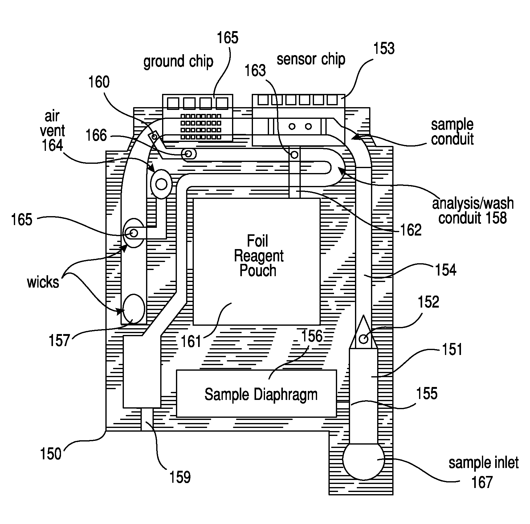
[0163]The present example describes a method of using a magnetic immunosensing device in accordance with one embodiment of the invention. As shown in FIGS. 30-33, an unmetered fluid sample was introduced into sample chamber 34 of a cartridge, through a sample entry port 4. Capillary stop 25 prevents passage of the sample into conduit 11 at this stage, and conduit 34 is filled with the sample. Lid 2 is closed to prevent leakage of the sample from out of the cartridge. The cartridge is then inserted into a reading apparatus, such as that disclosed in U.S. Pat. No. 5,821,399 to Zelin (referenced above), which is hereby incorporated by reference. Insertion of the cartridge into a reading apparatus activates the mechanism which punctures a fluid-containing package located at 42 when the package is pressed against spike 38. Fluid is thereby expelled into the second conduit, arriving in sequence at 39, 20, 12 and 11. The constriction at 12 pre...
example 3
Magnetic Immunosensing Device and Method of Use
[0167]The present example describes one of the methods of use of a cartridge. In this embodiment, the cartridge includes a closeable valve, located between the immunosensor and the waste chamber. For a cTnI assay, a blood sample is first introduced into the sample chamber of the cartridge. In the following time sequence, time zero (t=0) represents the time at which the cartridge is inserted into the cartridge reading device. Times are given in minutes. Between t=0 and t=1.5, the cartridge reading device makes electrical contact with the sensors through electrical contact pads and performs certain diagnostic tests. Insertion of the cartridge perforates the foil pouch introducing fluid into the second conduit, as previously described herein. The diagnostic tests determine whether fluid or sample is present in the conduits using the conductivity electrodes, determine whether electrical short circuits are present in the electrodes, and ensu...
PUM
 Abstract
Description
Claims
Application Information
 - R&D
- Intellectual Property
- Life Sciences
- Materials
- Tech Scout
- Unparalleled Data Quality
- Higher Quality Content
- 60% Fewer Hallucinations
Browse by: Latest US Patents, China's latest patents, Technical Efficacy Thesaurus, Application Domain, Technology Topic, Popular Technical Reports.
© 2025 PatSnap. All rights reserved.Legal|Privacy policy|Modern Slavery Act Transparency Statement|Sitemap|About US| Contact US: help@patsnap.com


