
Mega communication and media apparatus configured to provide faster data transmission speed and to generate electrical energy

a technology of communication and media equipment, which is applied in the direction of static indicating devices, instruments, high-level techniques, etc., can solve the problems of poor weather on microwaves, and achieve the effects of improving wireless internet services and satellite communications, and reducing the risk of electromagnetic radiation

Inactive Publication Date: 2012-02-09
TABE JOSEPH AKWO
View PDF15 Cites 146 Cited by
  • Summary
  • Abstract
  • Description
  • Claims
  • Application Information

AI Technical Summary

Benefits of technology

"The patent text describes a communication apparatus that aims to prevent cancer and improve the quality of life. It operates by converting sound waves, vibrations, solar energy, and pressure force into electrical energy and communicating it to a battery cell. The apparatus includes a media device, computer device, cell phone device, and hands-free cell phone and Internet application. It uses both one-way and two-way radio messaging methods, and provides feedback to improve communication efficiency. The apparatus also utilizes embedded chips and antennas to amplify signals and improve battery life. The communication apparatus is operable to transmit and receive information through microwaves, wireless Internet, and satellite communications. It provides easy communication methods and is hands-free while driving. The patent text also mentions the use of codes, such as the American Standard Code, for information exchange. Overall, the communication apparatus aims to enhance mobile communication efficiency and improve safety while driving."

Problems solved by technology

The chip is further operable to prevent wireless signal radiation, reducing exposure to cellular radio signals, which may cause health issues.
Some of the disadvantages of the microwave signal are the effect of poor weather on microwaves.

Method used


Image

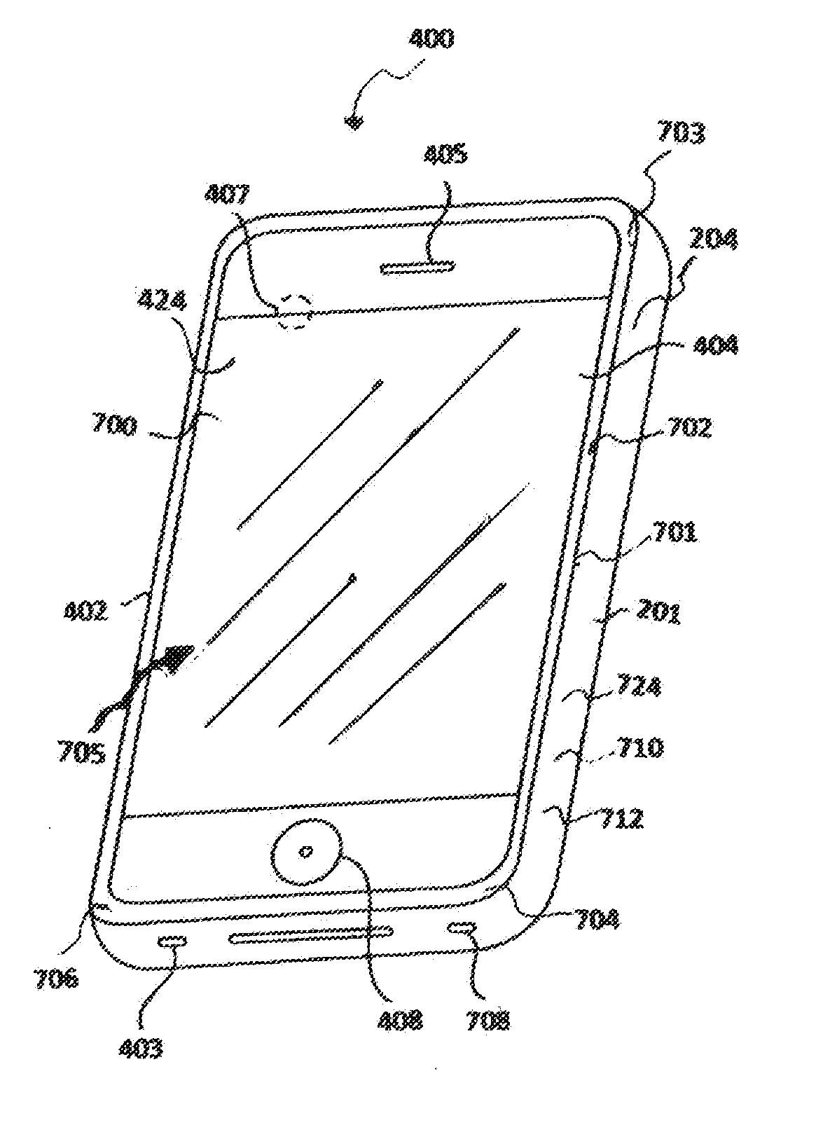
  • Mega communication and media apparatus configured to provide faster data transmission speed and to generate electrical energy
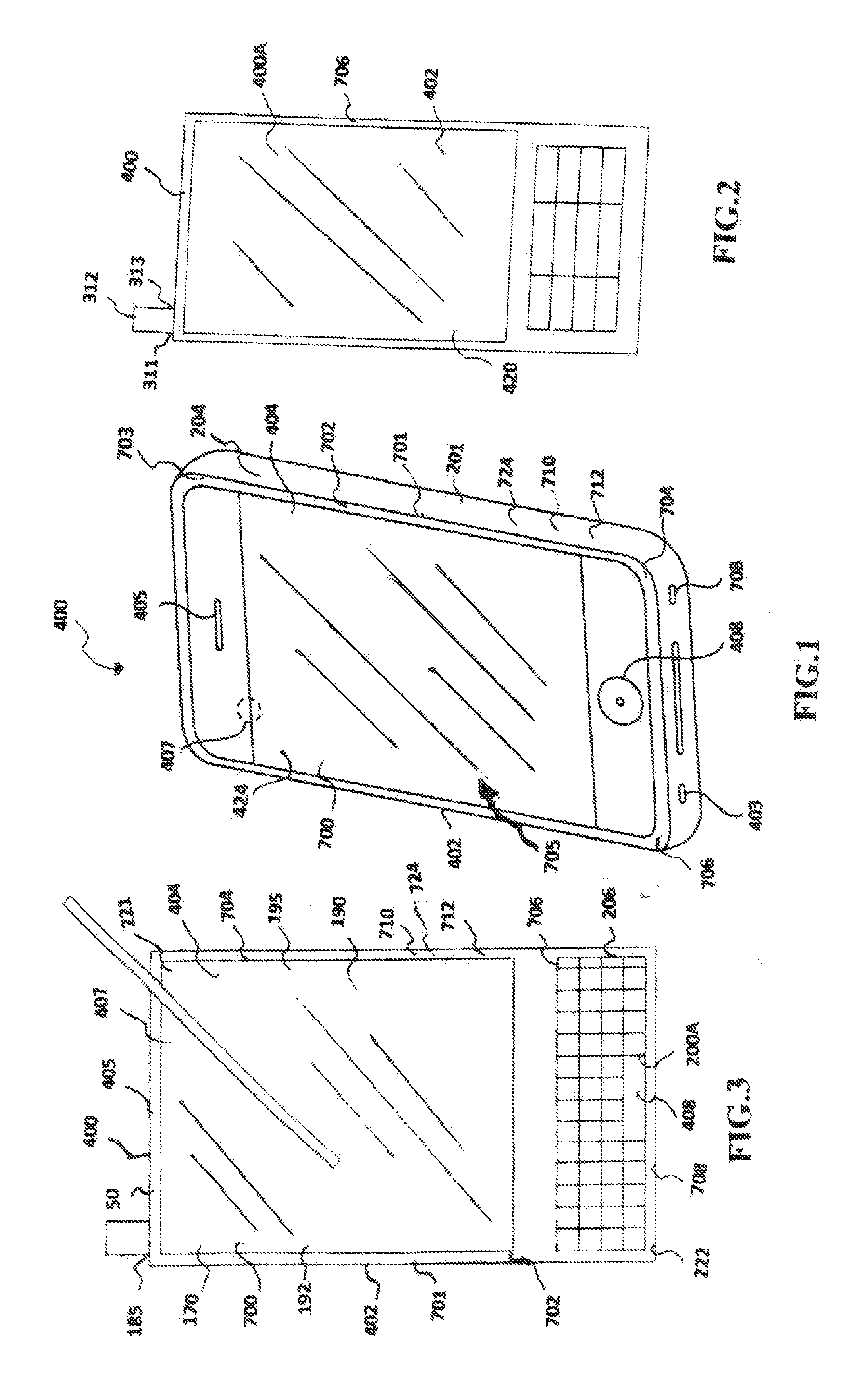
  • Mega communication and media apparatus configured to provide faster data transmission speed and to generate electrical energy
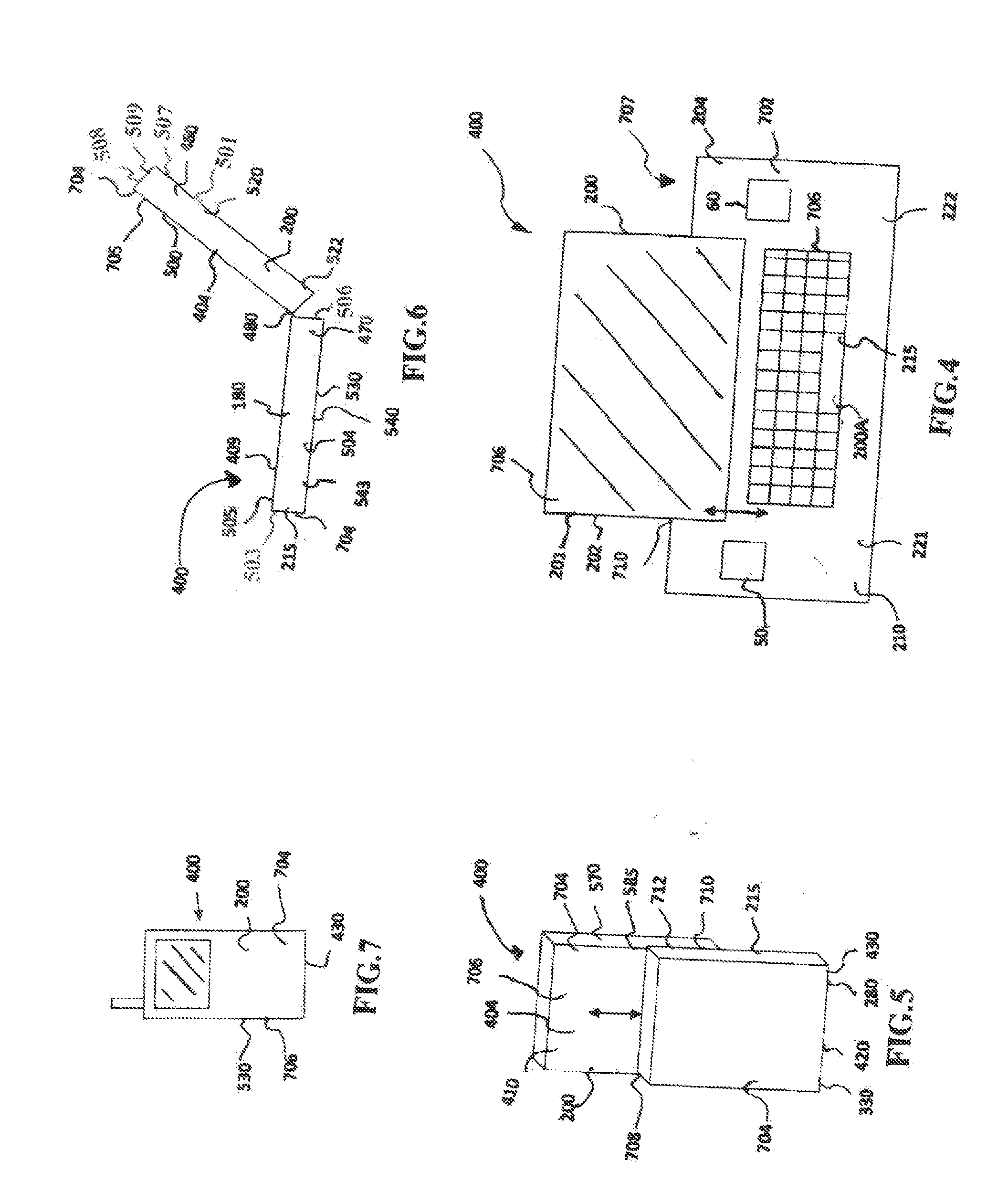
  • Mega communication and media apparatus configured to provide faster data transmission speed and to generate electrical energy

Examples


Embodiment Construction

[0086]The terminology used herein is for the purpose of describing particular embodiments only and is not intended to be limiting of embodiments. As used herein, the singular forms “a”, “an”, “at least”, “each”, “one of”, and “the” are intended to include the plural forms as well, unless the context clearly indicates otherwise.

[0087]It would be further understood that the terms “include”, “includes” and / or “including”, where used in this specification, specify the presence of stated features, integers, steps, operations, elements, and / or components, but do not preclude the presence or addition of one or more other features, integers, steps, operations, elements, components, and / or groups thereof. In describing example embodiments as illustrated in the drawings, specific terminology is employed for the sake of clarity. However, the disclosure of this patent specification is not intended to be limited to the specific terminology so selected and it is to be understood that each specifi...


PUM


Abstract

Disclosed embodiments comprise communication apparatus operatively configured with CMOS multiple antennas disposed on a chip for boosting communication signals to and for enabling faster data transmission speed and to provide interactive user interface. The communication apparatus is further configured to convert sound waves, vibrations, solar energy, wind force and pressure force into electrical energy communicable to a battery cell. Disclosed embodiment encompasses three modes of communications—the Cell phone, wireless Internet applications, and Global communication and media information. Embodiments provide communication apparatus operable to enhance mobile communication efficiency with touch sensitive display and provide energy harvesting platform on at least the housing for the apparatus and / or the circuit board configured with memories, processors, and modules. Embodiments provide advanced computing and media applications, including in-vehicle interactive communications and wireless Internet applications. Embodiments further provide a gaming device, a wireless media device configured with touch pads comprising sensors being embedded in silicon substrate and fused in micro fiber material having excellent electrical characteristics. Certain embodiments provide communication apparatus configured for voice enabled applications comprising human voice auditory operable to convert text into voice auditory and / or voice auditory into text applications.

Description

[0001]I HEREBY CLAIM PRIORITY BENEFITS FROM application Ser. No. 12 / 852,481, filed Aug. 7, 2010, which claims priority benefit from application Ser. No. 12 / 795,567, filed Aug. 7, 2010, which claims priority benefit from application Ser. No. 11 / 475,286, filed on Feb. 28, 2006, which is a continuation in part of Ser. No. 10 / 814,087, filed on Mar. 31, 2004, now U.S. Pat. No. 7,116,942, which is a continuation in part of Ser. No. 09 / 559,330, filed Apr. 12, 2000, now U.S. Pat. No. 6,782,240, which claims priority benefit from provisional application Ser. No. 60 / 131,134, filed Apr. 27, 1999. This application further claims priority benefit from application Ser. No. 11 / 821,776, filed Jun. 25, 2007 and has been allowed, which is a continuation in part of application Ser. No. 10 / 660,473, filed Sep. 12, 2003, now U.S. Pat. No. 7,271,720, which claim benefit from provisional application Ser. No. 60 / 426,800, filed Nov. 18, 2002. Application Ser. No. 10 / 995,093, filed Nov. 24, 2004, which has be...

Claims


Application Information

Patent Timeline
Patent Type & Authority Applications(United States)
IPC IPC(8): H01Q11/12H04W88/02G09G5/00
CPCH04B1/3838H04W88/02H01Q21/28H01Q1/243H01Q1/245H01Q1/2283Y02D30/70
Inventor TABE, JOSEPH AKWO
Owner TABE JOSEPH AKWO
Learn More